JET ENGINE POWERED SCOOTER

It seems that we humans have a strange fascination with strapping immensely powerful jet engines onto objects that were clearly never made for such propulsion, but that doesn’t stop the engineering (and a bit off kilter) minds of the world from giving it a go anyway. We’ve seen jet-powered wheelchairs and even supermarket carts, but the current king of overkill in regards to horsepower is none other than Ron Patrick — his rocket-infused Volkswagen Beetle, though deemed “completely street legal” by Ron, sports an extra 1,350 horses thanks to the massive blaster he attached to his ride. Obviously this little endeavor went over so well that he figured strapping dual JFS 100 jet engines onto his wife’s Honda Metropolitan scooter would solve her complaints of it “only going 40 miles per hour.” Since Ron estimates that one engine alone could get her ride over 60 mph, it’s fairly safe to say she should be outrunning commuters (and police, or anybody else for that matter) in no time. Patrick’s biggest challenge is compensating for the weight of the actual engines, because at 50 pounds apiece, they put a serious strain on the suspension. He plans to install an “air-start” that utilizes a “carbon fiber tank of compressed air” in order to remove the batteries currently on the vehicle. Regardless of Ron’s sanity (or lack thereof), we can’t argue with his determination, and if you happen to see a scooter in California with a curious looking device on each side (click through to see what we mean), don’t even think of revving your puny engine at Mrs. Patrick.


Enhanced by Zemanta

Achieving Better Fuel Economy and High Performance with Gasoline Direct Injection

Trying to choose between performance and economy is often a very difficult decision, and usually there has to be a compromise between the two. However, one technology is helping to power gasoline engines to new heights of performance, while pushing fuel mileage forward by leaps and bounds: gasoline direct injection. The photos below from Bosch illustrate the key elements of a gasoline direct injection system.


Back in the Day

Direct fuel injection is not a new idea. Diesel engines have always used the technology, which squirts fuel under high pressure into an engine’s cylinders rather than into the intake manifold. In a diesel engine, the process of injecting fuel directly into the combustion chamber at the top of the compression stroke initiates and controls combustion. The Robert Bosch Company perfected the modern mechanical injection pump for small diesels in Germany in 1927.
Bosch developed the first automotive direct injection system using gasoline, and Mercedes introduced it on the 1955 Mercedes Benz 300SL. Engine power was double that of its carbureted counterparts and allowed a top speed of up to 161 mph, making it the fastest production car of its time.

How Direct Injection Works

It might be easiest to see how direct injection works by comparing it to traditional fuel injection methods. With conventional fuel injection, injectors supply all cylinders with a mist mixture of air and fuel, averaging a constant 14.7:1 ratio, known as astoichiometric mixture. Vacuum draws the mixture into the cylinder where the spark plug ignites it. The throttle valve determines how much of the air/fuel mixture enters each cylinder, keeping the mixture at an optimum 14.7:1 ratio. Lean air/fuel mixtures won’t ignite well, creating excessive NOx and hydrocarbon emissions which the catalytic converter must then capture and process.
In a direct injection engine, the injection nozzle is located inside the combustion chamber and injects a finer spray, like that from an atomizer bottle. Each solenoid-controlled injector has minute outlet holes which exude a fine mist. Injectors positioned to the side of each cylinder, aim the fuel into the cylinder, adjacent to the spark plug, and alongside the intake and exhaust valves.

Like an atomizer bottle spray, the fine mist generated by each solenoid-controlled injector’s tiny outlet holes creates a well-atomized air/fuel mixture. Injectors spray fuel into the cylinders at pressures of up to 2,150 psi, about 35 times more intense than port fuel injection. (Courtesy of Bosch.)

A high-pressure fuel rail feeds each bank of cylinders using individual injectors and a fuel rail pressure sensor to help the powertrain control module precisely control fuel pressure. Some systems fire the injectors multiple times during one injection event at pressures of up to 2,150 psi, which is about 35 times more intense than port fuel injection.

Each bank of cylinders has a high-pressure fuel rail that feeds the individual injectors, and a high-pressure pump with a rail pressure sensor that helps the vehicle powertrain control module precisely control fuel pressure. (Courtesy of Bosch.)

When the injectors spray fuel into the cylinder, a relatively small, precisely-shaped volume of ignitable air/fuel mixture surrounds each spark plug. Areas inside the combustion chamber, but away from the spark plug, merely contain air or recirculated exhaust gas. This stratification of the charge allows the engine to burn mixtures with a much higher rate of air than conventional engines. The cushion of non-combustible gas around the combustion chamber also means less combustion heat to evacuate. This improves the thermal efficiency of the engine, increasing fuel economy.

To control injection valves, new common-rail injectors use a rapid-action actuator made of piezo crystals. Piezo package movement is transmitted non-mechanically and without friction to the rapidly switching nozzle needle. This doubles the injector’s switching speed, allowing a more precise measurement of fuel injected, and thus reducing harmful combustion by-products.  (Courtesy of Bosch.)

Since direct injection charge stratification works best at low and medium loads in the lower half of the engine speed range where traditional gasoline engines are least efficient, it allows direct injection engines to obtain up to 21 percent better fuel economy.

How Working Together Improves Performance and Economy

The future of direct injection involves coupling the system with other technologies, such as turbocharging and automatic engine stopping and restarting. By integrating multiple technologies, automakers can develop smaller, more fuel-efficient engines, while improving performance.
Turbocharging direct injection engines is a promising fuel economy technology. A turbocharged, direct-injection engine combines existing and proven technologies, allowing manufacturers to meet future emission standards using existing catalytic converters. Automakers can apply this technology across a manufacturer’s entire engine portfolio, including flexible fuel applications.
Other technologies maximize direct injection engine thermodynamics. In economy mode, an insulating blanket of air and recirculated exhaust gas helps keep heat away from the cylinder walls and head. In high-powered mode, the engine creates more heat. By controlling the operating speed of the water pump, especially during economy mode operation, a reduction in drag on the engine provides improved fuel economy. Variable intake and exhaust timing is especially efficient with gasoline direct injection and turbocharging systems. The variable engine timing enabled by camshaft phasing can optimize the combustion process. Also, valve overlap at low rpm can be adjusted by the engine controller to increase the turbocharger response, reducing turbo lag.

Servicing

With almost every manufacturer offering at least one direct injection engine, technicians should be seeing these vehicles in their bays for service.
“The biggest item to consider when servicing (direct injection) systems is the high voltage and fuel pressures the systems generate,” says Al Krenz, director of service for Bosch North America. A direct injection system typically will operate between 725 psi up to 2050 psi, so bleeding down the fuel system properly is important.”
“Always follow the manufacturer’s procedure to relieve the fuel system before performing any repairs to the system,” Krenz recommends.
Carefully diagnose the fuel injector voltage signals. High-pressure injectors typically actuate at approximately 70 volts and 10 amps, with the capability to rise over 120 volts.
As with diesel direct injectors, carbon can build up on the injector tip and interfere with fuel distribution and atomization. While typical port injectors produce a fuel droplet of approximately 165 microns, direct injectors atomize a much smaller fuel droplet size of only 65 microns, so even the slightest loss of fuel delivery will adversely affect engine drivability, power output, fuel economy and exhaust emission.

Enhanced by Zemanta

How to Repair Small Engines part1-Small Engine Basics

English: Animation of a 4-stroke engine showin...Image via Wikipedia


Small gas engines serve us in many ways. They power lawn mowers, tillers, cultivators, trimmers, edgers, snowblowers, chain saws, pumps, generators, air compressors, and other useful home tools. They also power our fun: outboard boats, snowmobiles, motorcycles, all-terrain vehicles, ultralight aircraft, and other toys. To keep them operating efficiently, an owner of these tools and toys should know about small engines: how they work and what to do when they don’t.
Small gas engines are made up of individual systems that work together to produce power. Each system has many components. Internal combustion gasoline-powered engines require six systems: fuel, exhaust, ignition, combustion, cooling, and lubrication. In this article, we will discuss the systems and components that make small engines work.

Fuel and Exhaust

The fuel and exhaust systems are critical to operation. They furnish the fuel for combustion and remove exhaust gases. The following are components of a fuel and exhaust system.
Gasoline: Gasoline is a combustible liquid that burns relatively slowly. However, when sprayed as a mist and mixed with air, it is quite explosive. All it needs is a spark. Two-stroke engines require that oil be mixed with the gasoline to lubricate internal parts. Four-stroke engines use a fuel-air mixture.
Fuel Tank: The fuel tank stores fuel in preparation for mixing by the carburetor and use by the engine. Some fuel tanks are pressurized with air to help deliver fuel to the carburetor. Other tanks are non-pressurized and depend on a fuel pump to deliver fuel to the carburetor.
Fuel Line: Fuel is moved from the tank to the pump and/or carburetor through a fuel line. Pressurized fuel systems often have a squeeze bulb in the fuel line for building pressure.
Filter: A carburetor jet has a small opening that can easily become clogged. A fuel filter traps dirt and sediment from the gas before it is delivered to the carburetor.
Pump: A fuel pump produces a vacuum that pulls the fuel from an unpressurized tank, then delivers it to the carburetor.
Carburetor: The carburetor has one job: to mix the correct proportion of gasoline and air for the engine. Too much gasoline in the mixture makes it rich; too little gas makes it lean.
Throttle: The throttle controls the amount of fuel-air mixture that enters the engine from the carburetor. The throttle thus controls the speed of the engine.
Primer: A primer injects a small amount of gasoline into the carburetor throat to make the initial fuel-air mixture rich. A primer is used to help start a cold engine.
Choke: Some engines control the richness of the fuel-air mixture at startup by controlling the air rather than the fuel. A choke reduces the amount of air in the fuel-air mixture.
Governor: A governor is a device that automatically opens the engine’s throttle when more power is needed and closes it when the load is light.
Muffler: Small gas engines, especially two-stroke engines, are noisy when they operate. A muffler reduces the sound of the exhaust gases by passing them through baffles.
Spark Arrestor: A spark can exit the exhaust port of a small gas engine, potentially starting a fire on nearby combustibles. A spark arrestor on the exhaust port can reduce the chances of such a fire. Spark arrestors are especially important on chain saws, motorcycles, and all-terrain vehicles operated in dry woodlands.

Ignition

The ignition is a primary system within all small gas engines. It produces and delivers the high-voltage spark that ignites the fuel-air mixture to cause combustion. No spark means no combustion, which means your engine doesn’t run. Below are the components found in small engine ignition systems. Some systems will include breaker point ignitions while others depend on solid-state ignitions.
Magneto-Powered Ignition System: A magneto uses magnetism to supply electricity in ignitions where there is no battery. The magneto is turned by the crankshaft, which rotates when the manual recoil starter is pulled. The three types of magneto ignition systems are mechanical-breaker, capacitor-discharge, and transistor-controlled.
Battery-Powered Ignition System: If your small engine includes a battery for starting, the ignition coil will also use it to supply spark to the spark plugs. A battery stores electrical energy until needed. Battery ignition systems also use mechanical-breaker, capacitor-discharge, and transistor-controlled ignitions.
Mechanical-Breaker Ignitions: High-voltage electricity must be sent to the spark plug at the appropriate time. In mechanical-breaker ignitions, this job is performed through the contact points and a condenser.
Points: As the crankshaft rotates, a cam opens and closes a set of contact points. These points function as an on/off switch: Closed is on, and open is off.
Condenser: Because the spark moving across points can damage their surfaces, the condenser stores voltage to reduce arcing between points.
Capacitor-Discharge Ignitions (CDI): A capacitor is a large condenser. A CDI stores and delivers voltage to the coil using magnets, diodes, and a capacitor
Transistor-Controlled Ignitions (TCI): Transistors are electronic controllers. A TCI uses transistors, resistors, and diodes to control the timing of the spark.
Coil: An ignition coil is simply two coils of wire wrapped around an iron core. The coil changes low voltage (6 or 12 volts) into the high voltage (15,000 to 30,000 volts) needed by the spark plug.
Spark Plug: A spark plug is an insulated electrode that is screwed into the top of the engine cylinder. High-voltage timed electricity from the magneto travels by wire to the spark plug. The base of the plug has an air gap of about 0.030 inch (30 thousandths of an inch), which the current must jump.
Wires: The primary wire from the coil to the breaker point and secondary wire from the coil to the spark plug(s) deliver electricity to the ignition components.
Distributor: A distributor is an ignition system for engines with more than one cylinder and spark plug. It distributes the spark to the appropriate cylinder using a rotor, cap, and individual spark plug wires.

Combustion

The combustion system of a small gas engine is where the work gets done. Components of the combustion system include the cylinder block, cylinder head, camshaft, valves, piston, connecting rod, crankshaft, timing gears, and flywheel. To better understand small gas engines, let’s look at how this vital system works.
Cylinder Block: The largest single part in a small gas engine is the cylinder block. It is a piece of metal in which the cylinder hole is bored or placed.
Cylinder Head: The cylinder head is the top, or ceiling, of the cylinder and is attached to the block with bolts. Depending on the type of engine, the head may or may not include valves.
Piston: A piston is the movable floor in the combustion chamber. Its upward movement compresses the fuel-air mixture. After combustion, its downward movement rotates the crankshaft.
Crankshaft: An engine’s crankshaft is a metal shaft with an offset section onto which the connecting rod is attached. Rotation of the crankshaft moves the piston up in the cylinder. Movement of the piston down in the cylinder then rotates the crankshaft.
Connecting Rod: Between the piston and the crankshaft is a connecting rod. At the larger end of the connecting rod is a bearing that allows rotation around the moving crankshaft. The small end is attached to the piston pin.
Valves: Valves simply open and close passages. A reed valve in a two-stroke engine is activated by changes in air pressure.
Flywheel: At the end of the crankshaft is a circular weighted wheel called a flywheel. The flywheel delivers the engine’s power to devices (wheels, blades, etc.) and helps keep the crankshaft turning smoothly.


Cooling and Lubrication
Combustion and friction produce heat. Heat and friction — if not controlled — can quickly damage an engine’s components. Small gas engines are typically cooled by air. Friction is reduced using movable bearings and lubricants.
Air-Cooling Fins: For simplicity, most smaller gas engines are cooled by air. Metal fins around the outside of the combustion chamber help dissipate the internal heat.
Friction: Friction is resistance that occurs when one surface rubs against another. Friction causes wear. In an engine with many moving parts, friction is reduced with bearings and lubricants.
Bearings: A bearing is a replaceable part that takes the brunt of the friction. A friction bearing relies on lubricants to minimize friction. A nonfriction bearing uses hard steel rollers or balls to prevent wear, though it too requires some lubrication.
Lubricants: Lubricants such as oil and grease reduce surface friction by coating parts with a film. Lubricants in two-stroke engines are applied to surfaces by mixing oil with fuel.
Viscosity: An oil’s viscosity is its resistance to flow. The thicker a lubricating oil or grease is, the higher its viscosity number.
Filters: Friction happens. Moving parts wear, even with the best lubricants. The resulting metal as well as carbon from the combustion process must be cleaned from the oil to ensure long lubrication. Some small engines use oil filters to remove contaminants from the circulating oil.
Regularly servicing your small engine will ultimately save you money and time. In the next section, we’ll review how, where, and when to service this engine.


The Benefits of Regular Small-Engine Maintenance

Purchasing a small engine-driven implement can make a dent in your budget. Tools and toys powered by small engines can cost anywhere from $100 to $10,000. That’s why it’s a good idea to invest in periodic servicing of your small engine. Replacing an engine every couple of years is an annoying and needless expense. Below we will review detailed information on how to service two-stroke gas engines. Following these procedures could help you put more money in the bank and less into your mechanic’s pocket.

Benefits of Regular Service

Servicing your small engine tool or toy on a regular basis offers many advantages over the Wait-Until-It-Breaks Maintenance Program.
  • By establishing a service schedule, you will gain confidence that whenever you need the unit it will be ready for use.
  • By performing a number of service functions together, you will save time. You can pick up all needed parts and lubricants in one trip to the parts store. Then you need to disassemble a component only once to perform numerous service procedures rather than taking it apart many times.
  • Regular service gives you a chance to visually inspect the entire engine and related components for damage, wear, and other potential problems.
How, Where, and When to Service Knowing how to service is as important as knowing when. Some service procedures can be performed wherever you store your tool or toy: in a garage, storage shed, or tool shed. If the unit is heavy, you can build a ramp up to a sturdy table that is at a handy height for working. Or you can use a ratchet winch to lift the engine. Units weighing less than 40 pounds may be lifted to a workbench or table as long as you lift with your legs rather than with your back. Get help if you need it, and make sure that the unit will remain sturdily in place as you service it. Remember to always put safety first!Servicing a small engine is easy once you know what to do and when to do it. A service chart can help you determine common service requirements as well as track what service has been done. Your engine-powered unit may have a service chart in the owner’s manual or service manual. Typical recommendations include changing engine oil every 25 hours of use and tuning up the engine at least once a year.The purpose of ongoing service, also known as preventive maintenance, is to keep your engine-driven tool or toy in good operating condition. Ongoing service procedures include air cleaner service, crankcase breather service, cooling system service, muffler service, lubrication, and tune-up.Lubrication service means making sure that all moving parts have sufficient lubrication (oil and/or grease) to minimize wear. Lubrication service procedures include mixing oil with fuel in two-stroke engines, and lubricating other moving parts.A tune-up consists of the adjustment and/or replacement of parts critical to smooth and efficient engine operation. Those parts include components in all engine systems: fuel, exhaust, ignition, combustion, cooling, and lubrication. Ignition tune-ups are more important for mechanical-breaker ignitions than they are for self-contained solid-state ignitions. Regular tune-ups will keep your small engine running smoothly and reduce the need for repairs.In addition, you should check other systems and make adjustments as needed to keep them operating smoothly. This includes adjusting the throttle, choke, and governor linkage, and cleaning off debris.Engine-driven tools and toys usually come with an owner’s manual. While some manufacturers’ manuals are more complete and better written than others, most manuals include basic information on safe operation and service. Unfortunately, product manuals are often written to reduce the manufacturer’s liability for accidental misuse rather than to help the owner service the product. In addition, manuals for engine-driven products typically show how to service the nonengine components: the grass catcher, wheel adjustments, blades, chains, and other parts. Service information for the engine may be minimal or nonexistent in the owner’s manual.
What can you do about this lack of information? Fortunately, there are numerous after-market publishers of service manuals for specific models of small engines. If you don’t have an owner’s manual, you can contact the manufacturer directly to purchase one; manufacturers also sell service manuals. Most manufacturers keep product manuals for up to 20 years. If they only have one original copy left, you can often request a photocopy for a small charge.
Knowing how to service the fuel system is an important part of caring for a small engine. Learn how to care for fuel filters, carburetors, and other major fuel system parts in the next section.

Enhanced by Zemanta

Four-Stroke Carburetors – Jetting

  Four-Stroke Carburetors


Your basic thumper carburetorYour engine is basically an air pump, and your carb meters how much air and fuel are sucked into that pump. Even though they may differ wildly in size, shape and design, all four-stroke carburetors have the same basic parts or circuits. Your slide cutaway (or throttle valve) needle and needle jet will all affect your bike’s acceleration from one-quarter to three-quarters throttle, and this is the most important area for off-road riders, since we spend the most time at these throttle settings. Due to the hassle of making changes to these circuits, these are the most neglected areas of tuning. Too rich jetting (too much cutaway, needle positions too high, too large a needle jet) can make your bike lunge and hard to control. If it’s too lean in this area, the bike will feel really flat and down on power, but will respond quickly to changes in throttle position. It may detonate (ping) under a load too. Pinging can also be caused by too little octane or winterized fuel (oxygenated, blended with additives), so keep in mind any fuel changes if your bike suddenly starts detonating in otherwise “normal” conditions.


Your main jet is probably the most talked-about circuit, and it’s as critical to get it right on a four-stroke as with a two-stroke. The main kicks in at half throttle and takes over metering duties as you hit full throttle. If your main is too rich, the bike will sputter and surge as it tries to burn all of that fuel. Too lean, and the bike will run flat or have a flat spot in the powerband. A severely lean main will cause your bike to seize just like a two-stroke. It’s better to be slightly rich on the main than slightly lean, because it will run cooler.


Yamaha’s new 400s have an accelerator-pump circuit. This system squirts a stream of raw fuel into the carb venturi every time you wick the throttle. Think of it as the four-stroke’s PowerJet carb – it richens the mixture to run best at lower engine speeds, yet allows a leaner top for more over-revs. If you radically modify your engine (flowed head, hot cam, etc.), you may have to richen this circuit slightly, but it’s otherwise not something you mess with for mere weather or altitude changes.


Your pilot jet (or slow jet) controls the idle circuit, or from zero to one-quarter throttle opening. The pilot jet and airscrew control the amount of fuel and air going into the engine at slow engine speeds. It’s very important to tune these circuits because they control throttle response and starting. The pilot circuit has a major affect on how well your four-stroke starts -or refuses to start – after a fall. At every event we attend, there is always some four-stroke rider who comes into the pits with his bike revving wildly. Invariably, this rider will say that his bike is hard to restart after a stall, so he turns up the idle adjuster so it won’t die.


That’s like jumping from the frying pan in to the fire. Thumpers are only hard to start when they are jetted poorly or when the wrong technique is used. The rider who turns up his idle is only perpetuating the myth about thumpers being hard to start. Most manuals (and this magazine) tell you that you should not touch the throttle when you kick a thumper. Well, turning the idle up is mechanically opening the throttle, right? You will make, your bike even harder to start. You have to fix the problem, not the symptoms of the problem!


General Carburetor Jetting Tricks
Your bike’s owner’s manual is a great source for recommended jetting and tuning tips. If you bought your thumper used and don’t gave a manual, get one. Set the idle speed as per your manual. If it won’t start easily using the manual’s technique, your pilot jet is the likely culprit.


Whether your bike is air or water cooled, you should start it and get it up to race temperature before tuning the pilot circuit. A hotter engine will run leaner than an old one, so failure to properly warm the bike will result in a too-rich setting. With the bike up to temp, adjust the airscrew so that the bike runs and responds best to slight throttle movements. Now, kill the motor and see how many turns out you have on the airscrew. Less than one, and your pilot is too lean. More than two, and it’s too rich. Install the next-size pilot and repeat the test.


Most off-road bikes are jetted lean to meet emissions standards, so you will likely want to richen these circuits, especially if you have gone to an after-market pipe, air filter or even removed OEM baffles (pipe and/or airbox). If you remove the muffler diffuser, you should toss the airbox stuffer too, or the airbox won’t be able to draw enough air to feed the engine. Most aftermarket companies will give you recommended jetting, so use this as a baseline.


Under most conditions, about the only time you will need to go leaner on an EPA-legal four-stroke is because of altitude. Air is thinner at higher altitudes, so it contains less oxygen, and your jetting will be too rich. You will want to go down a size on the pilot, one or two on the main and lower the needle a position (raise the clip).


Cold air is denser than warm air, so it holds more oxygen. On cold mornings, your jetting will be slightly rich, but thumpers are less susceptible to changes than two-strokes. Where you might change the pilot on a two-stroke when it’s really cold, an airscrew adjustment will suffice on a thumper.


The same is true for barometric pressure. As the barometer rises, the pressure compresses the air, and your jetting will be slightly lean. A falling barometer causes a rich condition, but thumpers don’t care about the weather as much as two-strokes.


Four-Stroke Carburetion Troubleshooting
Overall, the Yamaha YZ400F is jetted almost perfectly from the factory; however, it is very picky about its air filter. Do not over-oil the filter, and do not expect it to start immediately after oiling the filter. Let it sit overnight (not in the cold) to allow the carriers to evaporate. Better yet, keep spare filters in a plastic bag so that you never put a freshly oiled filter in the bike on race day. Modifications throw stock jetting out the window, so this troubleshooting guide will apply to the 400F as much as any other four-stroke.


Bike Won’t Start After a Crash
  • Pilot too lean
  • Idle set too high
  • Improper starting procedure
  • Bike wants hot-start button (KTMs and 400Fs)
Bike Runs-On or Won’t Idle Down When Throttle is Chopped
  • Idle set too high
  • Air leak in intake or engine
  • Pilot too rich (when bike is hot)
Bike Wont Start When Cold Temp Outside
  • Pilot jet too lean
  • Air filter over-oiled
  • Motor oil too thick for temperature

Bike Sputters / Wont Clean Out at High RPM
  • Main jet too rich
  • Air filter over-oiled
  • Spark plug has debris on electrode
Bike Coughs & Stalls in Slow Turns
  • Pilot jet too lean
  • Idle set too low
  • Valves set too tight
  • Decompressor is set too tight, so turning the bars engages release slightly
Bike Hesitates or Bogs Over Deep Whoops or G-Outs
  • Float level too low
  • Carb vent tubes blocked
  • Main jet splash shield not installed
  • Float level too high, gas is trapped in vent tunes (install T-vents)
Bike Starts But Wont Take Throttle Without Sputtering
  • Pilot jet too rich
  • Water in fuel
  • Debris in main jet
Bike Suddenly Starts Sputtering / Gas Flows from Vent Tubes
  • Stuck float check valve
  • Debris in gas or carb
Bike Runs Hot / Feels Slow & Flat on Straights
  • Main jet too lean
  • Fuel octane too low, causing detonation
Bike Coughs & Stalls When Throttle is Whacked Open
  • Needle too lean
  • Slide cutaway too lean
  • Pumper circuit blocked or too lean
Enhanced by Zemanta

Understanding Carburetion – By: Canadian Dave


 Carburetor Tuning

Understanding Carburetion
Motorcycle carburetion is fairly complex, but a basic understanding of the parts and theory involved will go a long way to simplify the processes and make fine-tuning your carburetor much less intimidating. Right off the bat I’m going to say this is only intended to be a very basic explanation. Motorcycle carburetion is quite complex with a number of circuits and conditions acting together to deliver a measured amount of gasoline and air to your engine. Most of which aren’t even mentioned here. To do it justice you would literally have to write a book and that’s not my goal here. Information from a 1988 to 2000 KDX200/220 Keihin PWK is illustrated here but the principals are the same for all KDXs.

Basic Motorcycle Carburetor Theory
Pressure can be your friend. Your KDX relays on differences in air pressure to deliver a charge of gasoline and air into the engine. If you measured the force applied by a column of air above the Earth you’d find that it exerts about 15 pounds of pressure per square inch at sea level. This pressure is referred to as atmospheric pressure and varies slightly with altitude, meteorological (weather) conditions etc. but we’ll talk about that later. Air, gasoline etc. will move from an area of higher pressure to an area of lower pressure until both are equal.
How does your engine produce a pressure differential? As the piston moves past bottom dead center ( its lowest point ) and back up towards top dead center ( its highest point ) the pressure above the cylinder increases and the pressure below the cylinder decreases. The reduced pressure inside the crankcase causes the reed valve to open and outside air, at a higher pressure, to flow through the carburetor delivering a charge for gasoline and air to the engine’s crankcase, which is at a lower pressure. Great so we know how air is drawn through the carburetor and into crankcase but what about the carburetor how is gasoline combined with the incoming charge of air?

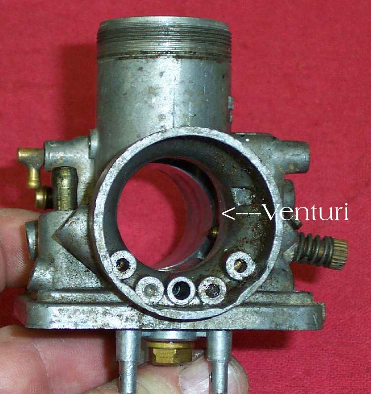
Some times restrictions can be a good thing. If you place a restriction in the path of a flowing liquid or gas a drop in pressure is created. The pressure before the restriction will be greater than the pressure after the restriction. Yup we’re back to that pressure differential thing again. Since the charge of incoming air must pass through the horn shaped mouth of the carburetor and into the smaller venturi ( a restriction ), the pressure before the venturi is higher than after. Such a reduction in pressure will cause an increase in the airs velocity because the same amount of airflow must take place before the restriction as after it. Velocity will vary directly with the amount of flow, and as the flow increases a greater pressure differential will occur across the venturi.

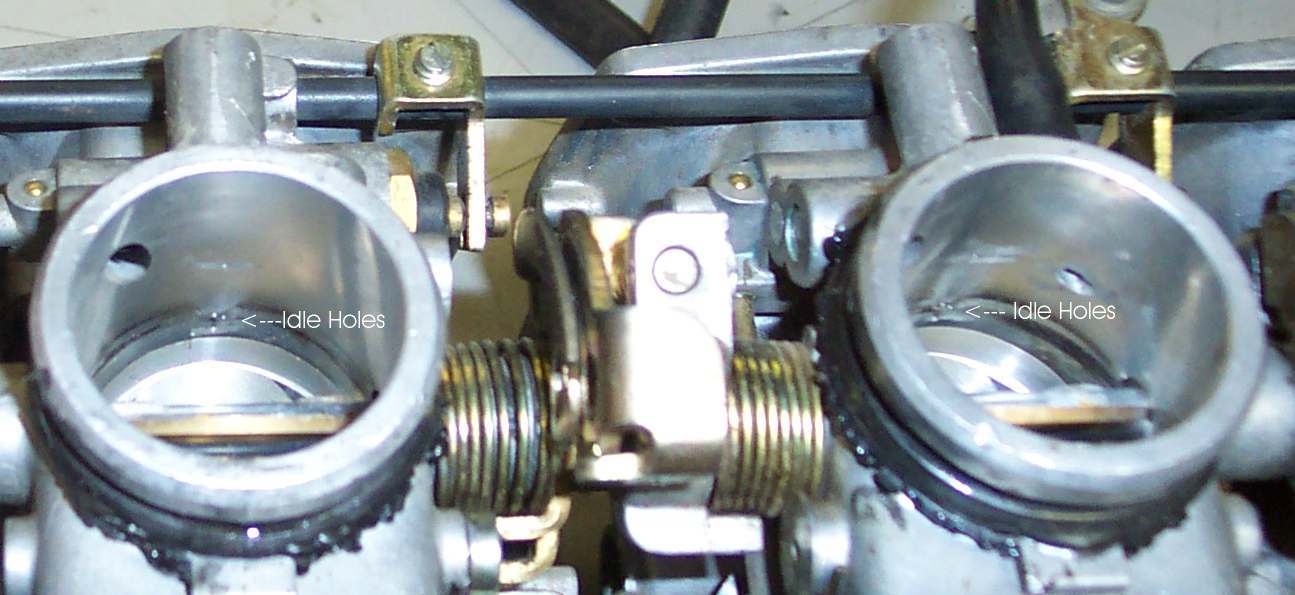
Ok so we know that as air is drawn into the carburetor and meets the restriction imposed by the venturi a pressure differential is created. The atmospheric pressure outside the carburetor is greater than the pressure inside the carburetor. So why do you care? Because the carburetor’s float bowl is vented directly to the outside atmosphere (higher pressure) and connected to the venturi (lower pressure) via the pilot circuit and the needle jet/ spray bar ( through the main jet ) that’s why. If we remember that a liquid, gas etc. will move from an area of higher pressure to an area of lower pressure until both are equal we can see how gasoline is introduced into the incoming charge of air. In this case gasoline is forced from the float bowl up through the pilot and main jet into the carburetor’s bore where it is delivered to the crankcase. 

Jetting

The Basics- When people talk about jetting a carburetor, tuning a carburetor or “breaking out the brass” they’re talking about manipulating the carburetor’s 4 main circuits to optimize gasoline delivery and therefore engine performance. They might adjust the air screw, adjust the jet needle’s clip position or exchanging the pilot (slow) jet, main jet, throttle valve (slide) or jet needle for one of an appropriate size. A perfectly tuned 2-stroke engine/carburetor delivers a 12.5 to 1 air to fuel ratio.

The Parts- No jet acts independently of the others but rather they work together to deliver gasoline to the engine. They do however target specific throttle openings and have the most effect is that area. See below.

The air screw is most effective between idle through 1/8 throttle.
The pilot (slow) jet is most effective between 1/8 through 1/4 throttle.
The slide valve is most effective between 1/8 through 1/2 throttle
The jet needle is most effective between 1/4 through 3/4 throttle.
The main jet is most effective between 3/4 through wide-open throttle.

 Before we get into the different parts of the carburetor and how they effect gasoline delivery I want to stop for a second and define the terms RICHER and LEANER. I know these terms can cause some trouble for those who are new to the sport or new to carburetor tuning and they are often used incorrectly. The terms RICHER and LEANER refer to the amount of GASOLINE being delivered to the engine and not the amount of oil. If you’ve done a plug reading at wide open throttle and the plug indicates you are running rich ( dark brown to black ) this is an indication that too much gas is being delivered to the engine and not too much oil. I know there are people that will say “You’re running too rich, try to change your premix ration from 42 parts gas: 1 part oil ( 42:1 ) to 50 parts gas : 1 part oil, that should lean things out a little “. This is in fact increasing the amount of gasoline ( 8 more parts of gas for each part of oil ) and causing the engine to run RICHER rather than leaner. If you remember richer and leaner are referring to the amount of gasoline being delivered this will all make much more sense.
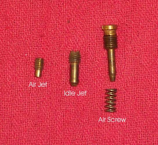
The pilot, or slow circuit, can be adjusted by manipulating two parts: the air screw and the pilot jet. The air screw controls the flow of air into the circuit. Turning the air screw clockwise reduces the air flow and richens the circuit.  Turning it counter clockwise increases the airflow and leans the circuit. You can therefore use the air screw to fine tune the pilot circuit. The pilot jet restricts/regulates the flow of gasoline from the float bowl to the venturi. Pilot jets have a precisely machined orifice/hole running through their center which gasoline passes through. Increasing the size of the pilot jet ( size of the hole ) richens the circuit by supplying more gasoline; i.e. removing a 40 pilot jet and installing a 42 richens the circuit.

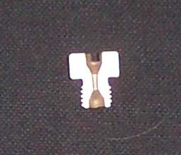
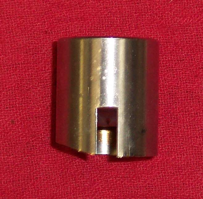
The slide/throttle valve has the most effect between 1/8 and 1/4 throttle with a declining effect up to 1/2 throttle. The throttle valve can be exchanged for one with a greater or smaller cutaway. The PWK equipped KDX200/220 comes equipped with a #5 or 5mm cutaway. The larger the cutaway the more air flows to the jet block/nozzle screen leaning the mixture. Exchanging the factory #5 ( 5mm cutaway ) throttle valve for a #6 (6mm cutaway) would lean the mixture.

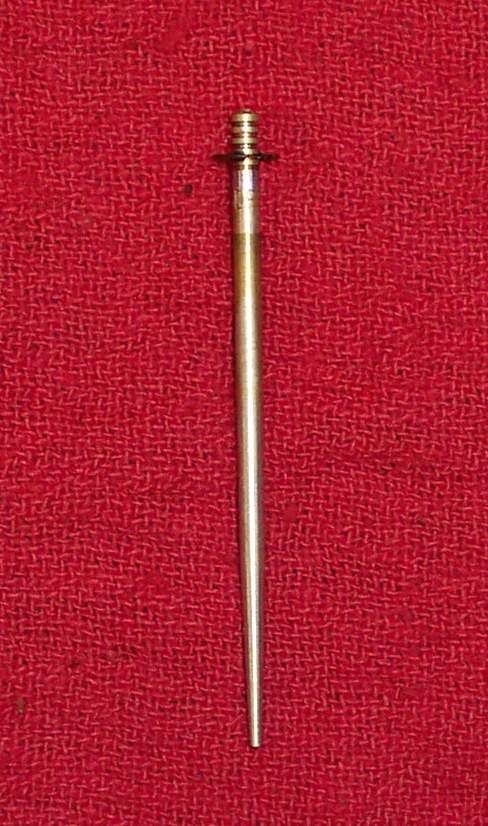
The jet needle – Has the greatest effect between 1/4 and 3/4 throttle. It’s attached directly to the throttle valve. As the throttle is rolled open or closed the jet needle moves through the needle jet’s bore exposing different sections of the jet needle’s profile to the needle jet’s inner bore.
Six major elements determine the jet needle’s effect on fuel delivery – the diameter of the straight section, the length of the straight section, the jet needle’s taper, the clip position, the number of tapers and the length of each tapered section. The number of tapers is normally not changed from what was supplied from the factory. 

jetneedle.gif (2936 bytes)

I’ll talk about jet needles in greater detail in the Tuning section.

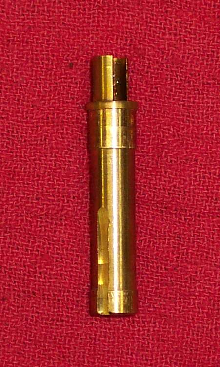
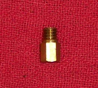
The Main Jet- regulates the flow of gasoline from ¾ to Wide Open Throttle. Like the pilot jet the main jet has a precisely sized hole drilled through its center. Increasing the size of the main jet ( size of the hole ) richens the circuit by supplying more gasoline; i.e. removing a 152 main jet and installing a 155 richens the circuit.

Tuning
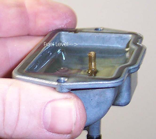
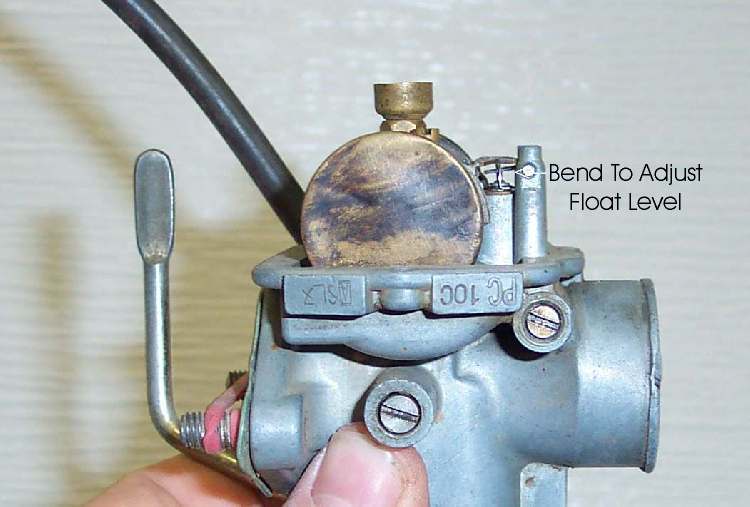
Before you consider fine tuning your carburetor there are a few things that have to be done. First you need to install a clean air filter. Second you need to insure the float level is properly set. If the gasoline level is set too high or too low properly jetting your bike will be impossible. A high float level will cause it to run rich and a low level cause it to run lean. You can find instructions for setting you float level here.
Third you need to fill your tank with a fresh load of premixed gasoline. Don’t go out and try to jet your carburetor with the gasoline that’s been sitting around in your jerry can for the past month. Gasoline degrades over time so you’ll want to start with a fresh batch. While I’m talking about gasoline remember that different gasoline will change your jetting requirements. If you normally run race gas, straight or use it to cut pump gas, you’ll want to be sure you have it in your tank when you head out to tune the carburetor.
You also need to be aware of any potential mechanical problems that can imitate poor jetting. Eric Gorr has included a number of articles on his web site from his book “Motocross and Off- Road Motorcycle Performance Handbook”. An excellent article on carburetor tuning is included which covers this topic. Check it out here. If you don’t own a copy I’d definitely recommend picking one up. It’s chucked full of useful, easy to read information and make a great companion to your factory service manual.
When making jetting changes make one change at a time and test the result. It’s very helpful to keep a log book for your motorcycle where you can log changes to the jetting, the temperature, altitude etc and the result. Over time you’ll build a jetting history of your bike that you can go back to and determine what changes you have made. I also include routine maintenance and repairs in my log book.
Tuning From Idle to Wide Open Throttle, Plug Reading – Again this is a good method for beginners. Once you’ve gained more experience and are more comfortable with jetting you’ll start to relay more on power delivery and how the engine feels until then this is a good method.
If you go back and have a second look at the parts of a carb you’ll see that gasoline delivery is dependent on throttle position and not engine speed. You’ll also notice that the air screw, pilot jet, main jet, and jet needle target specific throttle setting. With this information in hand we can easily identify which circuit is likely the cause of a specific symptom.
Before you head out for a jetting session you’ll want to mark your throttle grip and housing so you can easily identify the four major target ranges. I like to use White Out but placing a piece of tape on the throttle grip and throttle housing and breaking out a marker will work just as well. With the throttle at idle and your materials in hand draw a straight line across the inner cuff of your throttle grip and onto the throttle housing. Now twist the grip to WOT and draw a second line on your grip straight across from the line on your throttle housing. Next find the half way point between the two and place a third line, this will indicate ½ throttle. Now divide the halves in half again and mark 1/4 and 3/4 throttle. Now with a quick glance you can easily determine the throttle position while jetting.
Now’s a good time to stop and talk about plug reading. The color and condition of the spark plug can tell you a lot about what’s happening in your engine. You’ll be doing some runs at known throttle settings and then observing your spark plug to determine the condition of the corresponding circuit i.e. is it lean, good or rich. Ideally a professional tuner would use a variety of instrumentation and how the engine feels to fine-tune jetting. For more information on instrumentation check out Eric Gorr’s comments on “How to use carburetor tuning gauges. This method will insure you’re in the ballpark so you can start fine-tuning. When you have more experience and are more confident in your ability to determine jetting requirements by feel you’ll start to phase out this method for 1/4, 1/2 and 3/4 throttle setting and replace it with the jetting by feel method. You’ll continue to use this method for tuning the main jet at WOT. I’ll also say that my recommendation for the appearance of a good plug is going to be slightly different than someone who is jetting a motocross bike for an experienced rider. The conditions faced by enduro riders and moto-cross riders are quite different and therefore the jetting requirements are also slightly different.
Checking the Main Jet– Warm up the engine and go for a short ride letting the engine comes up to its normal operating temperature. Install a brand new plug that’s been properly gapped. With the new plug installed aggressively accelerate through the gears until you reach 4th or 5th gear. For best results you should accelerate up a slight up hill section to place additional load on the engine. Continue to run the engine at WOT for 20 to 30 seconds longer if there is not fear the engine is running lean. If you suspect the engine is running lean 15 to 20 seconds to give you an indication. At the end of your full throttle run simultaneously push the kill button, chop the throttle and pull in the clutch. This procedure is often refereed to as a ” plug chop”. It is important to perform a plug chop exactly as described. If you allow the engine to run or leave the throttle open for even a few seconds after the plug chop the plug reading will be invalid. Now remove the spark plug and carefully look at its color.

Plug Reading – What does a good plug look like? First you need to know where to look and what to look for. I’ve seen a lot of plug reading instruction that suggest you to look at the general appearance of the plug. That doesn’t work. The easily visible portion of the plug, the upper part of the porcelain and the electrodes, won’t give you an accurate reading. This area is mostly affected by additives in the gasoline and the oil you’re running. To get an accurate indication you want to look down inside the plug where the porcelain insulator emerges from the steal body of the spark plug. Ideally you should see a ring of light brown/tan at the lower 1/4 of the porcelain. White is lean and you’ll need to install the next richer main jet( larger number ) and do another plug reading. A dark brown to black ring is too rich and you’ll need to install the next leaner main jet ( smaller number ). A small flashlight and magnifying glass make this much easier to see and it’ll give your friends something to poke fun at. If you ride in a diverse area with fluctuations in temperature greater than 15 degrees F, and altitude changes dropping more that 3000 feet over the course of the day or you ride in high load conditions ( loose sand, mud, long steep hills ) adjust the size of your main jet until you reach the ideal condition then install the next richer main jet which should result in a dark brown plug reading. You’ll be loosing a small amount of top end power in trade for the added confidence that you can ride aggressively over the course of the day without fear of running lean at WOT.

Checking the Jet Needle – Once you have the main jet properly sized you can turn your attention to the jet needle. Warm up the engine and go for a short ride until the engine comes up to its normal operating temperature. Install a brand new plug that has been properly gapped. With the new plug installed accelerate through the gears until you reach 4th gear. For best results you should find a location that allows you to run safely at half throttle with out having to ex or decelerate to avoid obstacles etc. A long straight away or well groomed oval track will work the best. Continue to run the engine at half throttle for more than 60 seconds if possible. Do a plug chop and inspect the plug. If the plug indicates a lean condition, lower the clip on the needle by one position. Lowering the clip by one position raises the needle further out of the needle jet allowing more gasoline to flow, richening the circuit. If the plug is dark brown to black raise the clip’s position by one notch to lean the circuit. As a general rule if you need to run the clip in the top position you should install a leaner jet needle. If you need to run the clip in the bottom position you should install a richer  jet needle. Jet needle selection is something of an art. Watch for an article in the near future describing PWK jet needle profiles in more detail.  This method will give you a good ball park indication if you jet needle is properly sized.  However due to inefficient cylinder scavenging at lower throttle settings its often little more that a ball park indication and you’ll need to fine tune by feel.
Once you’re satisfied with the appearance of the plug turn to the jetting by feel method to fine-tune the circuit. Gradually roll the throttle open from 1/2 to 3/4 throttle paying particular attention to the sound and the type of power delivery. Having an experienced friend on the sidelines to listen and watch the silencer for excessive smoke is also helpful. A rich condition will result in excessive smoke from the silencer, the plug will often carbon foul and the engine will produce a sputtering/crackling sound. A lean condition will result in slow throttle response, you twist the throttle but the power delivery is lethargic and flat. A lean condition results in a tell tale booooooha sound as well. You can quickly verify a lean condition by pulling the choke half way out. Engaging the choke will deliver additional fuel to the system and the symptoms of a lean condition should clear up.

A Helping Hand
There’s a little tip that’ll make changing needle clip positions a breeze. If you’re like me you tire of wrestling the throttle valve spring and collar pretty quickly when it comes time to adjust your needle. Not to mention the first time you sent a spring loaded collar jettisoning into a dirty mound. Why is it those ” must stay clean” parts always find there way into the grim anyway? This little trick makes trail side needle adjustment anxiety a thing of the past.

clampsm.jpg (13929 bytes)
Run to your local tool supply store, hobby shop or what have you and pick up a hemostat. I’m not talking about the bone crushing size here, a 4 to 5 inch pair will work just great and they’ll only set you back $4 to $5. The best thing about a hemostat is its small enough to carry in your fanny pack and they apply just enough pressure to prevent the spring and collar from slipping but not enough to damage the throttle cable. Nurse, hemostat please!

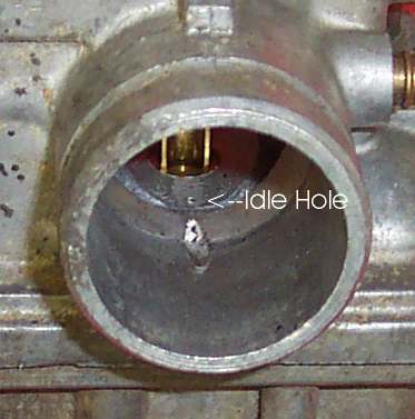
The Pilot Circuit, Tuning from Idle to ¼ Throttle –You can use the air screw to help determine if your pilot jet is appropriately sized. Take your bike for a short ride letting the engine come up to normal operating temperature. With the engine stopped, transmission in neutral and the bike on its stand turn the air screw clockwise until it just seats, gentle now it’s delicate and you don’t need to torque it down just gently seat it. Now turn the air screw a quarter of a turn out so the engine will fire and start it.  Slowly turn the air screw counter clockwise ( out ) until the point where the engine just reaches the maximum obtainable rpm and continuing to turn the air screw beyond this point wont increase the engine speed (rpms) any further. I find it’s easier to hear the rpm increasing if you set the idle at its lowest possible position without the engine stalling. You’ll want to repeat this procedure a couple times until you’re confident that you’ve found the right spot and that the result is reproducible. When you’re comfortable count the number of turns ( 360° revolutions ) you’ve backed the air screw out to reach this point. The normal operating range is between 1 and 1.5 turns out so if you find the ideal setting is less that 0.75 turns out consider installing the next richer pilot jet (larger number ). If you find the ideal setting is more than 2 turns out consider installing the next leaner pilot jet ( smaller number ).
Once you’re comfortable you have an appropriate pilot jet installed you want to fine turn the circuit using the air screw. Starting with the air screw 0.5 turns out adjust the screw an 1/8 of a turn at a time until you’ve obtained the best possible throttle response between idle and 1/4 throttle. Continue to adjust the air screw until the engine’s throttle response off idle is clean with no hesitation or bogging. You can test the final results using the same method as you did for checking the jet needle this time riding in 2nd or 3rd gear at 1/4 throttle. Remember this is only a ball park indicator your goal here is to obtain the best possible throttle response not a perfect plug reading.
Because jets have a combined effect over a range of throttle setting its often useful to go back and recheck your jetting once you have followed this procedure. The second time through you can broaden the throttle settings to insure there’s a good transition between one circuit and another. So for example slowly roll the throttle open between 1/2 and WOT insuring the transition is progressive and that the engine doesn’t stumble etc. Do the same between 1/8 and 1/2 throttle, 1/4 and 3/4 throttle etc.

The Effect of Temperature, Altitude and Humidity on Jetting
Once your jetting is set it’s not necessarily set for life. Changes in air temperature, altitude and humidity can have an effect on how your engine runs.
If you captured a measured volume of air on a humid 90° F day at sea level or a cool dry 40° F day at 10,000 feet both would contain about 22% oxygen. The density and therefore the total number of oxygen molecules however would differ enough to effect the performance of your engine.
Temperature- For most of us changes in air temperature will have the greatest effect on our jetting. As the air temperature gets colder the air density increases. The air molecules become less active ( move around less ) and therefore take up less space. Because they take up less space more air, and therefore more oxygen, can fit into a measured volume of air as the temperature decreases. As the temperature drops the engine will begin to run leaner and more gasoline will need to be added to compensate. As the temperature increase the engine will begin to run richer and less gasoline will be needed.

Altitude- Again this is an issue of air density. At sea level atmospheric pressure is around 15 psi and as the altitude increased the atmospheric pressure decreases. Because less pressure is exerted on a measured volume of air as the altitude increases the air molecules are able to relax and they take up more space leaving less space for additional molecules. The higher the altitude the less air in a measured volume and therefore less oxygen present so jetting will have to be leaned to compensate.

Humidity– Humidity is a measure of how much water vapor is in the air. The higher the humidity the less space there is for additional molecules of air and therefore oxygen. As the humidity increases there is less oxygen and therefore the engine runs richer. Jetting that may have been spot on in the cool dry morning air may start to run rich as the temperature and humidity increase over the course of the day.

Correcting for Changes in Temperature, Altitude and Humidity
Correction Table-You can use a correction table to roughly determine the appropriate jetting changes to compensate for changes in temperature, altitude and humidity. I’ve included a typical correction factor chart that has been modified specifically for use with the KDX. To use the chart go back to your log book and record what jetting is presently installed in your carburetor then determine what altitude you’ll be riding at and the temperature. I’m assuming here that you’ve already optimized your jetting.  I’ve used my present jetting as an example. You’ll need to slightly modify the table to fit the specific requirements of your bike but I’ll go over that in the example.

Example- I’m presently running a 45 pilot jet with the air screw 1.25 turns out, an 1173 jet needle in the second from the top clip position and a 152 main jet. This jetting was optimized at 20° C and 2240 ft above sea level. For this example lets assume I’m going riding in the mountains where the temperature is 20° C at 9600 ft. The first thing I do is adjust the bottom of the table so that it reflects the condition where my jetting was optimized. Using the illustration below as an example I draw a straight line from 20° C horizontally across the graph until I hit the line that represents 2240 ft., then draw a line vertically to the bottom axis on the graph. This point becomes 1.0. Adjust the work sheet by subtracting 0.02 for each increment to the left of this point and adding 0.02 for each increment to the right of this point. My graph now looks like this:

Now using my personalized graph I can calculate what jetting I should install before making the trip to the mountains. I draw a horizontal line from 20° C over to 10000 ft and then vertically down to determine the correction factor of 0.95. To find the correct pilot jet size I multiply 45 by 0.95 and the new jet size would be 42.75. The closest available size is a 42 and I’ll fine-tune the pilot circuit with the air screw once I get there. I then multiply my main jet size ,152, by 0.95 and the new jet size would be 145.  Now remember this is intended to give you a rough indication.  
You can print off your own correction factor table here.
Using a correction table should allow you to closely meet the requirements of changing conditions. It is however intended to be used as a guide. You should always carry an assortment of jetting in your toolbox and check any jetting suggestions you receive. At a minimum do a plug reading at WOT after changing your jetting to insure you aren’t running lean. Jetting recommendations that work well for one bike may not necessarily work for another even if it is being ridden in the same area with identical modifications.

Available Keihin Jets – Tle main and pilot jets for yhere’s a list of availabour reference. I’ve included jets sizes commonly used to fine tune PWK equipped KDXs. This includes 1988 to 2000 KDX200/220 as well as second generation KDX250s. There are larger and smaller sizes available that aren’t listed here. This list might seem rather long but it includes possible jet sizes for a number of temperatures, altitudes as well as modified cylinders.
“21 Series” Pilot Jets – 38,40,42,45,48,50,52
” 13 Series ” Main Jets – 140,142,145,148,150,152,155,158,160,162,165,168,170,172,175,178,180

Jetting Recommendations, a Starting Point
These are intended to be good jetting STARTING POINTS so use them as just that a starting point. In many instances jetting will be very close if not right on but you’ll need to insure you’re not running lean and optimize the jetting from here to meet your individual requirements. At the very least you’ll need to do a throttle reading at Wide Open Throttle and insure you’re not running lean.
These jetting  recommendations are intended for use between sea level and 3000ft with an average temperature of 73 degrees plus or minus 7 degrees.

1995-2001 KDX200

Stock -Run the stock R1174K jet needle in the second from the top clip position, 45 pilot jet, 155 main jet and fine-tune the pilot circuit using the air screw.
With a performance pipe/expansion chamber, the air box lid removed and the stock or a performance silencer run a 42/45 pilot, R1174K jet needle in the mid clip position, a 152/155 main jet fine tune the pilot circuit using the air screw.

1997 to 2001 KDX220

  Stock run a 42 pilot jet,the stock R1173L jet needle in the second from the top clip position, a 142/145 main jet and fine tune the pilot circuit using the air screw.
With a performance pipe/expansion chamber, air box mods ,  the factory or after-market silencer and the stock 33mm carburetor run a 42 pilot, the stock R1173L jet needle in the second from the top clip position, a 145/148 main jet and fine tune the pilot circuit using the air screw.
Same as above but with your carburetor bored between 35 and 36mm or running a 1988 to 2000 KDX200 35mm carb jet according to 95 to 2000 KDX200 requirements.
Addition of Boyesen reeds or a Boyesen RAD Valve will require you to lean the pilot and main jet one size and readjust your air screw.

1989 to 1994 KDX200

Stock -Run the stock R1172N jet needle in the second from the top clip position, 48 pilot jet, 155 main jet and fine-tune the pilot circuit using the air screw.
With a performance pipe/expansion chamber, the air box lid removed and the stock or a performance silencer run a 45/48 pilot, R1173N jet needle in the mid clip position, a 152/155 main jet fine tune the pilot circuit using the air screw.
Addition of Boyesen reeds or a Boyesen RAD Valve will require you to lean the pilot and main jet one size and readjust your air screw.

For jetting recommendations on remaining models ( 1982 to 1988 KDX200s ) check out Jeff Fredette’s engine performance recommendations 
If you require addition jetting help fire your question off to the JustKDX Forum. You’ll need to include the following information; year, model, modifications ( things like after-market reeds, pipe, air box lid mods, silencer, ported cylinder etc etc. average riding conditions, air temperature ( don’t submit a range between 5 and 85 degrees F you need to beak it down into your present condition within 10 degrees C or about 15 degrees F. ) altitude and average humidity.
Enhanced by Zemanta

how to clean your carburetor the proper way

I get asked about Carburetor Cleaning regularly both from readers and from friends offline. So I’ve decided to write a definitive guide for cleaning carbs the RIGHT way. So put your tools down for a minute, grab a beer, and give this a read. You might just save yourself a lot of headache and sweat.
Carbs come in many shapes and sizes. Single carbs, dual carbs, racks of 3, 4 or 6, V racks, carbs with ticklers, carbs with accelerators, carbs with asynchronous designs, and carbs that operate vertically. While working on some carburetors is more difficult (due to design) than others, they all share the same basic components, and the process of cleaning those components is generally indentical.
BEFORE YOU START
Make sure that dirty carbs are actually your problem. Lots of things can make a bike run poorly or not start. Weak battery, corroded electrics, old spark plugs, bad timing, low compression, mis-adjusted valves, dirty air filter, and plugged exhausts can all cause poor running. I’ll write an article on how to diagnose poor running conditions shortly, but for now – lets just deal with the carbs.
OK, SO YOUR CARBS ARE DIRTY
Once it has been determined that the carbs are the problem it’s time to get to it. Some racks of carbs are easier to remove than others. If you’re working on a newer model bike the rubber boots from the airbox to the carbs and the manifold boots from the carbs to the motor should be relatively soft and pliable. On older bikes however this is rarely the case.
First remove the fuel tank, seat, and side covers. Depending on your model of bike other parts may need to be removed too. Â For many single cylinder bikes the carb can often be removed without removing any body work at all.
The bike below is a 1983 Yamaha XJ750 Seca with 4 inline Hitachi carburetors

1983 Yamaha XJ750 Seca Carburetors
Yamaha XJ750 Motor and Carbs

You’ll want to loosen the circle clamps on all of the rubber boots. Sometimes I’ll even take them all right off (carefully, without bending them too badly) so that they aren’t in the way.
Inspect the airbox. On many bikes it is bolted in place to tabs on the frame. Remove those bolts and try to create as much space as possible for the airbox to pull backwards.
Next, put the bike on it’s centerstand and straddle it facing forward. Put your right hand on the right-most carburetor and your left hand on the left-most carburetor and get ready to sweat. Sometimes you’ll be able to pull the carbs straight backwards nice and easy, but that is pretty rare. I usually end up rotating them up then rotating them down as best I can while pulling backwards furiously. This can really take some work and time, especially if you’ve never done it before. In real extreme cases where you simple can’t get the carbs to pull backwards out of the manifold boots I have a couple tips. These tips should only be used in extremely difficult cases when you have been struggling for an hour and simple can’t get the carbs to pull backwards out of the manifold boots.
Tip 1: Ratchet Straps – This is sort of a last resort, but it has worked without fail for me when I’m pooling sweat on the garage floor and the carbs aren’t budging. Wrap a ratchet strap around one of the outer carbs and put the hooks somewhere on the rear of the frame. Then slowly ratchet the carbs right out of the boots. Be careful not to pull them too cockeye’d or you could damage the boots. Attach a second ratchet strap to the other side if necessary. (Note: you can do this in the opposite direction to force carbs back into the boots once they are clean.)

Tip 2: Full Pull! – You should do this before you do the ratchet strap method above. Sit down on your butt along one side of the bike. Wedge one of your feet up between the forks and the front fender, then put both hands on the same outermost carb and PULL PULL PULL! This might not work so well if you’re short! Ha.

Ok, So The Carbs are pulled back

Chances are the airbox boots are all crammed up now. Do your best to rotate the carbs up and out from the boots and pull them out one side of the bike. Sometimes it’s easier to pull the carbs out one side than the other, so have a look to see if there are frame elements, motor elements, or hoses that may block the carbs from coming out on one side.

Also keep note of the throttle cable(s) and choke cable (if there is one). Now may be a good time to loosen the nuts that hold them in place and disconnect them.

Struggle just a couple more minutes wriggling the carbs out the side.

Ok, You have the carbs off the bike

Make sure you brush off any loose dirt or grime, then flip the carbs over and remove the screws from the corners of the carburetor. Some carbs won’t have bolts in the corner and instead have a wire latch over top which can just be forced over.

Remove the bowls.

If the carbs are real gummed up the insides might look like this:

It’s obvious that these carbs are all clogged up. Some carbs might not look so bad, some might be a lot worse. It’s always a mystery what will be inside the bowls.

Now it’s time to remove the floats. It’s generally a good idea to drench everything in carb cleaner (available at any autoparts store). Sometimes the pins will practically fall right out, sometimes they’ll be so stubborn you won’t think they’ll ever come free. But they will! Carefully push on the pin from either side. Sometimes a nail and a gentle tap from a hammer is helpful. **BE CAREFUL**, using force to remove a stuck float pin can break off the pin tower. If they are really stuck and you can’t seem to work them free here are a couple tips.

Tip 1: Heat – Adding a little flame to the float pin towers can help. **Don’t Burn Down Your Garage!!**

Tip 2: Pliers – Using pliers to gently clamp the end of the pin and push it through has worked well for me in the past. **Don’t break the towers!!**

Once the float pin is out you can remove the floats, the float needle, and unscrew the float jet screen.

Set everything aside. Next remove the main jet, pilot jet, and idle jet (if there is one). They should come out easily with a flathead screw driver.

Set them aside.

Next flip the carburetors back over and remove the caps. Underneath the caps is a rubber diaphram with a spring. Sometimes the caps have a tendency to shoot off the top, so be very methodical when removing the screws. Other times the cap tends to stick down until you start to pry at it, then it shoots off, again, just be cautious and don’t loose any parts.

Next you’ll want to gently pull the slides up out of the carburetor body. You can gently pull on the rubber diaphrams, but be very careful not to tear them. If they don’t come up easily stick your finger into the carb intake and push the slide up with your finger. You can also gently pry it with a screw driver (gently). If it doesn’t want to budge don’t force it. Instead finish reading this article and pay attention to the boiling tips further down.

Now your carbs should be pretty well emptied out. If the throttle on the bike moved fluidly and smooth there is little reason to do much to the carb bodies themselves. However, if the throttle was real sticky or frozen there are a few things you can do to free it up. Sometimes just drenching all the throttle components on the carbs and letting it soak is enough, other times it is not. I generally try not to break racks of carbs apart. It isn’t often necessary and can be confusing to put everything back together in the right places. Also, the little rubber connector hoses and o-rings have a tendency to crack or leak if you mess with them. If you can’t work the throttle back and forth until its smooth have a look at the boiling tips further down.

Keep it Neat

Organization pays off.

Clean the Main, Idle and Pilot Jets

Hold each jet up to the light and see if you can look through it. The idle and/or pilot jets have extremely small holes so make sure you are looking through them straight. If you can see through the jet it isn’t clogged. There could be a little gunk built up around the edges so spray them down with carb cleaner and let them sit a bit.

If you can’t see through the jet it is clogged and needs to be cleaned. Always try the easiest things first. Here’s an ordered list of a few things you can do to clean the jet.
Blow through it. – Rarely works, but hey, who knows.
Compressed air. – Force 100 pounds into it. Works occassionally. Make sure to hold the jet tightly so it doesn’t go flying across the garage. You might put the jet back into the carb body to hold it in place for this.
Soak it in cleaner. – When I first started cleaning carbs I thought carb cleaner would be the magic answer. It isn’t. In fact, I hardly ever use carb cleaner any more, because it simply doesn’t do a very good job of anything but removing varnish from the bowl and slide. But try this.
Poking it through. – Collect a few different diameters of needle like objects. A wire from a steel bristle brush works well, a bristle from a broom works well, a baby pin, small sewing needle, etc. Very gently try to poke it through the jet. If you are using a metal needle use caution, brass jets can scratch and deform easily.
Boiling! – This works better than anything. Toss the jets into a pot of boiling water and let them bounce around for a couple minutes. When you pull them out blow some compressed air through them and you’ll most likely be good to go.

Some idle jets can be real tricky and never seem like they’ll be cleaned out . . . Just keep working at it, I’ve never met a jet that couldn’t be cleaned.

Cleaning the Choke and Air Mixture Screw

Air mixture screws have a tendency to strip or break. If the carbs were real gummed up you might find that the air screws are stuck. Don’t force them, if they don’t want to come out, just leave them for now. It is fairly rare that these screws will need to be cleaned because they are above the float level. If you can get them out just wipe them down with carb cleaner and spray some through the jet.

Cleaning the Slide and Needle

These are easy to clean. Squirt them with a bit of carb cleaner, wd-40, or anything similar, then wipe them down with a rag. Once the varnish is gone they’re good to go. Sometimes they get heavy varnish on them which I will scratch off carefully with a piece of plastic. Scratching the slide and needle is a BAD thing, use caution.

Cleaning the Carb Bodies

Use the same squirt and wipe method noted above. Most of the time the other pressed jets and passages in the carburetors won’t be clogged. But if the bike has been sitting a real long time with squirrels in the airbox it is certainly possible. Us a compressor to blow some air into every passage you can see. Listen for the air coming out the other side. If no air compressor is available use a can of WD-40 with a straw attachment.

If some of the pressed jets are clogged it can be difficult to open them up. There are a few things you can do.
Carb Dip – Most autoparts stores sell carb dip. It comes in a can similar to a paint can and is a VERY harsh cleaning agent. Soak the entire carbs in this dip. This dip can eat at rubber and plastics if they are submerged for too long, so try and remove everything you can from the carb bodies before soaking them. Once you pull them out swish the carbs around in a bucket of water to clean off the excess dip, then hose them down with WD-40 to get rid of the water.
Boiling in Water – Not many people do this but it is by far the best way of cleaning carburetors. Dropping the carbs into a pot of boiling water will instantly free up stuck slides, throttle plates, and other frozen parts. It will also loosen the dirt and grime clogging up pressed jets and other passages. Just make sure to dry the carbs thoroughly with compressed air or the sun afterwards.
Boiling in Lemon Juice – There is NOTHING BETTER at cleaning carbs than a giant pot of boiling lemon juice. The acidity from the lemons eats through everything; gas varnish, oil build up, dirt, grime, etc. Sometimes I won’t even bother doing anything but this – I’ll just remove the bowls, remove the caps, then drop everything into the pot and let it sit for 20 minutes (rotate them a few times). The one caveat to doing this is that you’ll want to wash the lemon juice off the carbs as soon as you pull them out. So have a bucket of water ready, or a can of WD-40 to hose them down. Also note that the acidity has a tendency to put a dull finish on the aluminum bodies of the carbs. This isn’t a problem in most cases, but if you must have everything shiny be prepared to do a little scrubbing and polishing afterwards. It may sound weird, but trust me, I just saved you LOTS of time. (Most dollar stores sell 1/2 gallon jugs of lemon juice, so buying a few gallons will only cost you $6. Plus you can put it back into the bottles afterwards and save it for next time.)

Cleaning the Bowls

This is pretty straight forward. Use any of the methods above to tranform your varnished bowls.

Most carb bowls are simple, just clean them up and they are good to go. But I picked this Hitachi’s for photos because they have a jet built into the bowl. You can see the ‘fifth’ hole along the edge of the bowl, that is actually a thin passage that extends to the bottom of the bowl. This is for the idle jet and is extremely important. If these passages are clogged, the bike won’t stay running, period. Use the same poke, soak, and boiling methods outlined elsewhere in this article. Not all bowls have these passages, only some, if your’s don’t – good for you!

Once Everything is Clean

Now that everything is clean it’s time to put it all back together. Take your time and make sure you put everything back where it came from. WD-40 is your friend. When screwing in the jets don’t over do it, they only need to be seated and snug, do NOT use any force putting the carbs back together.

If the bowl gaskets got goobered up you can put a little RVT on them. So long as the float needles are still in good condition leaky gaskets shouldn’t be an issue. However, prudent carb tinkerers may want to order replacements if necessary.

Once the carbs are back together stuff them back into the bike!

Extra Notes
Rebuild Kits – This guide did not mention rebuild kits until now. Rebuild kits (consisting of new gaskets, jets, needles, etc) can be purchased for nearly any bike, both old and new. 95% of the time these are NOT needed. I have rebuilt enough carbs to block off main street, and only once have I used new parts. ONCE!
Carburetor Adjustment – Carburetor adjustment, setup, jetting, and synchronizing is a whole encyclopedia waiting to happen. Those topics are not covered in this article, but I will address them in future articles.
Carburetor Polishing – External carb asthetics will be important to some, and not to others. Cleaning is all I am covering here, this will be addressed in the future.
Work Space – Make sure you have lots of space to keep organized. I also like to work on a wooden surface because it absorbs the spilled gas and cleaners rather than pooling.

That’s it! You’re Done!

source

Enhanced by Zemanta

Fuel intake system – Basics


Dear Biker,
Are you tired of cold starts? Need to raise the throttle everyday to get the cold engine running?
Does someone have the same bike as yours and are you tired of losing to him in drag races?
Suddenly, the fuel efficiency has reduced after a service?
Has the mechanic has screwed up your tuning?
Engine gives hiccups when you open the throttle
Or your bike is just missing that smooth acceleration whenever you want?
Or your engine overheats even if you did not race too much.

May be the following will help you in tuning your mean machine for optimal power delivery and best fuel economy. This guide aims at tuning the fuel/air screw to give you an optimal air-fuel mixture. An optimal mixture gets maximum performance from your machine.
Getting The Basics

I am assuming that you know driving very well and have completed at least 1000kms on road. If not, then you are too amateur to read this guide.

Every bike has a engine (motor/mill/muscle) and a carburetor (breathing system/heart) – Yeah I know that. My point is, I assume that your engine is in perfect condition. That is, there is no oil leaking from it etc etc.. The next assumption is that your engine is not DEAD. You know where your engine is and where your carb is and you have a screw driver/blunt knife with you. Your machine must have finished at least one service ~500kms or more. Also make sure you do not change the fuel type while tuning i.e. Power, Speed, Extra premium, normal unleaded etc.
This Guide Applies To

All the single cylinder bikes, 2 stroke or 4 stroke having a carburetor. Tachometer is very handy and amust for a newbie or the tuning process will be very slow or painful or imperfect.

Disclaimer: Though whatever I have written here wont do any damage to your machine, finally you must not blame me for whatever happens. I am here to help if anything goes wrong.
So Lets Get Started

Warm the engine nicely. Go get a ride around the town. Speed nicely at least upto half the top speed of the bike. Drive at least for 10-15 minutes so the engine system warms up nicely or you’ll get a bad tune. Do not just leave the engine idle and start with process. I mean it. Ride the bike.

Now that the engine is adequately heated up, you are ready to begin with the process. You can select a place far away from the city or your residential area so that you do not disturb the tired, sick, disgusted, old people or babes (babies) living in your colony. You are likely to be shooed away from them when you are at a critical point. You may choose a place near your girl friend’s house just to impress her! Put the bike in main stand and get hold of your screw driver. That is all you need, together with your eyes, brains and ears.

Searching the fuel/air screw… The above mentioned screws are responsible to adjust the air-fuel ratio which forms ‘food substance’ for your engine. You can relate it to our human body, where proteins, carbs, fats, water etc all are required in appropriate proportions with respect to each other for good strong body.

There is another screw which sets the idle speed of the machine. This screw is not related to pickup or mileage. It just sets the engine rpm at ’’idle’’ run. 2stroke machines have an Air screw and 4 stroke machines have a Fuel screw. I hope you note this VERY well. Air screw is located on the carb away from the engine. [ Engine – Carburettor – Air screw]

Fuel screw is located on the carb but its near the engine. [Engine – Fuel screw – Carburetor]. If the make of your carb is Mikuni (Pulsar, Yamaha, Fiero) the fuel/air screw probably will be of brass (golden colour). If you fully unscrew this screw and take it on your hand, you will see a needle like tip.

Idle screw is closely linked with the throttle cable. Idle screw can be turned by the hand. Screw driver is not essential for it. Finding these screws are very simple. If you still cannot find the air/fuel screw, ask your mechanic or I can help.

Ok now what? Apart from the above difference I gave between Air and Fuel screw, there is one more major difference. Fuel screw turned in (clockwise) gives a lean mixture and turned out (anti-clockwise) gives a rich mixture. Air screw turned in gives a rich mixture and turned out (anti-clockwise) gives a lean mixture. Lean means more air, less fuel. Rich means more fuel, less air. This ends the basics.
Getting Things In Action

Turn the idle settings screw so that rpm reaches about 3000 rpm. Now tune the air/fuel screw to make the mixture leanest as possible. Please refer to the above whether you must turn the screw clockwise or anti clockwise.

As you make the mixture leaner, slowly the engine RPM decreases… Go on doing this until you have put the fuel screw to the leanest possible point. At the same time, ensure that the engine does not stall, by turning the idle-screw.

Tough huh? You’ll get used to it

OK the engine is running and the mixture is lean. If you notice from the engine sound OR if you see the tachometer, the engine RPM will not be steady at this point. Now very slowly start turning the fuel screw anti-clockwise, quarter to 1/8th turn at a time. You will notice that the RPM increases slowly and steadily. Again, do this very very slowly. Also count the total number of turns as you wind out the screw.

You’ll notice that when you have turned it to about 3-4 full revolutions, the engine RPM slowly becomes constant. It is this point that you must stop screwing more. This probably is the optimal setting for your engine.

Further on, try turning the screw even more and more to 5-7 revolutions and you’ll notice that the engine RPM will slowly decrease. When this happens, you are just putting in a too rich mixture in your engine. At this point the engine loses all the fuel efficiency and the mixture is not optimal. Repeat the process about 2-3 times. Count the revolutions each time and get the setting which you feel is correct.

OK the engine is humming perfectly, now what? Decrease the idle setting screw to about 1000rpm in the tachometer. When the engine slows down, just twist the throttle. The response should be crisp and quick. It should not give any hiccups! Try shutting off the engine and restarting. The engine MUST start in a single kick or self with out giving throttle. If this happens, the setting is ok. Now get a ride and you’ll notice the difference for good or bad

You’ll immediately notice change in the engine sound and the throttle response. Your engine can become more smooth or harsh. Another important point is, Ride and Feel. Always take a ride and get the feel of the bike in each gears, check the response and the engine sound. You’ll quickly come to know once you get the feel of the bike that you want to make the mixture rich or lean.

For some reason everyone seems to think tuning a carb is just real easy. Change a jet or two and boom, your there. Yeah, right ! There are quite literally millions and millions of jet combinations. A rough check on Bing carbs shows there are at least 13,860,000 different combinations of jets. If you are going to change carbs you’d better be prepared to spend some time and money on the job.

If you look at a carburetor, you will notice a rather large hole going from one side to the other. This is called a Venturi. Air passes into the engine through this hole (Venturi). As the velocity of the air entering the carb (and then the engine) increases, it’s pressure decreases, creating a low pressure or vacuum in the venturi. This vacuum moves around in the venturi, as the throttle is opened, and sucks gasoline through the different jets in the carb. The gas then mixes with the air going through the venturi. The way the jets are made causes the fuel to vaporize as it goes into the venturi. Where the jets are placed in the carb and where the jet’s outlet is located in the venturi, determines what part of the throttle opening that jet controls. The idle jet system (comprised of pilot air jet, pilot fuel jet and pilot fuel screw) controls from 0% to about 25% of the throttle opening. The throttle valve controls 0% to 35% of the throttle opening. The needle jet and jet needle control from 15% to 80% of the throttle opening and the main jet controls 60% to 100%. This means that when you open the throttle about one eighth of the way open, all of the gas/air mixture going into your engine is controlled by the idle jet. As you can see, the different jets over lap the operating range of each other. That is, the jet needle starts to effect things before the effect of the idle jet ends. This is something to remember when working on carbs… everything is interconnected. Change one thing and it will effect other things.

OK, let’s go over the different systems in the carb and see what they do.
Fuel level. The fuel level is controlled by the fuel floats and the fuel float valve. The floats are hollow or made of something that will float on gasoline, such as cork. Part of the float presses against the float valve, sometimes called a needle and seat. Most times the part of the float that touches the float valve needle is bendable so you can adjust the level of the fuel in the floatbowel. All plastic floats are not adjustable. If this level is way too high, gas can leak out the carb overflow tube or into the engine. If fuel gets into the engine it will thin out the engine oil, ruining it’s ability to lubricate. This will, sooner or later, blow up your engine ! If a full tank of gas in the evening turns into a half tank by morning, check your oil. If it’s thin and smells like gas, change it and replace your float valve and/or check your fuel level. If the oil is OK, check under the overflow tube. If it’s OK, then check where you are parking your bike ‘cuse someone is walking away with your gas !If your fuel level is just a bit high, the mixture will tend to be a bit rich. If it’s low, the mixture will tend to be a bit lean. This is because a high level takes less vacuum to suck fuel into the engine and a low level takes more vacuum to do the same.
Pilot or idle jet system. The idle jet controls the idle and on up to quarter throttle, give or take a bit. On some carbs, like Mikuni there is an air jet too. In conjunction with the idle jet there is an idle jet air screw. This screw leans or richens the fuel mixture for a smooth idle and on up to one quarter throttle. From the idle jet, there are little passages cast into the carb that lead to holes just in front of the throttle valve or plate. There can be just one hole or there can be several, depending on the carb design. They effect the mixture as long as the vacuum, in the venturi, is over them. As the throttle opens further, the vacuum moves to the needle jet and jet needle.
The Throttle Valve. The big slide that opens and closes your throttle has a bevel angle cut in one side of the big round (can be flat, too) slide, toward the air cleaner. This angle comes in several sizes and helps control the fuel mixture from idle to about 35% open throttle.
Needle Jet. This jet doesn’t really even look like a jet, but it is ! It controls the fuel mixture from 15% to 60% open throttle. It sets in the center of the carb, right over the main jet.
Jet Needle. This is the needle that rides in the throttle slide and goes into the needle jet. This needle controls the fuel mixture from 20% to 80% open throttle. It can come in many different sized tapers. Sometimes, one needle can have several tapers on it. The top end of the needle has grooves cut in it, usually five, and you can move the little clip on the end up or down to lean (down) or richen (up) the mixture. Most late model bikes have needles with only one groove cut in them. This is so you can’t richen the mixture, thereby keeping the EPA happy.
Main Jet. This jet controls the fuel mixture from 60% to 100% open throttle.

We want nice clean acceleration from idle to full throttle, with no stumbling or flat spots. This can be quite a tall order if we are starting with a new carb. Actually, it can be a real challenge to get things to carburate right after something as simple as an exhaust pipe change.

Now, I wish I could tell I’m the great carb man, but, well… no one has ever been dumb enough to hire me to really work over a carb. Well, there was that one time with that Kaw 650 and aftermarket pipes. It had some kind of weird stock carbs that looked like Mikunis but really were not. It had TDK or KDT or DTK, something like that, carbs. It had aftermarket exhaust pipes and was running too lean, and stumbled at one point under acceleration. Worthless pig ! The jet needles where not adjustable, so I put little washers under the needle clip, to raise the needles. The main jet only came in one size, so I drilled it out with ity-bity, expensive, jet drills. I could move the miss around, but I could not get rid of it. From the beginning I told the guy it wouldn’t work and that he was wasting his money, and that at the least we needed carbs we could get parts for, but nooo. Just rise the needles, drill the jets he said… $200 later he finally gave up. I guess I shouldn’t complain, I did get paid… but !

But you want to try it, don’t you ? OK, the drill really isn’t that hard. Simply run the engine at whatever throttle opening you want to test, for a mile or so, and look at the spark plug. Is the spark plug reading lean or rich ? Now look for the jet that controls that particular throttle opening and exchange it for a richer or leaner one. Now that doesn’t sound very hard, does it ? Oh yes, the throttle transition from one jet to the next must be smooth too ! Go back over the areas that each jet controls. They overlap each other. Some a little, some a lot. Make sure you have a good selection of jets ! Most carb manufacturers have tables of specifications on the jet needles and needle jets, and other jets that you will find very useful. With these specs you can make a better guess as to what jet will work best. Some places use motorcycle dynamometers for testing. These can be a big help to get real close to the best jet setting. Working out the best main jet for a 170 MPH bike can be quite unhealthy if you only have a freeway to test on ! Just remember one thing. A dynamometer is not the real world. A fact more then one factory has found out the hard way when their super hot, dyno tested, race machines didn’t run so fast in the real world, on real pavement, in real air with real bugs on the windscreen !

Anyway, what I’m trying to get over to you is that just because your buddy said he got new carb, changed a jet or two and now his bike gets 100 miles per gallon and has double the horse power, doesn’t mean you can too ! It just might require a lot more work than you bargained for.

Look on the bright side. Carbs used to be real simple at the turn of the century, but they didn’t work as good as today’s carbs.

Oh, one last thing, seeing how we are talking carb theory. When an engine is cold, like when you first start it up. It doesn’t evaporate the gas well. Liquid gas does not burn, so you have to put in lots of gas, because a lot of it does not vaporize. The choke helps the carb to put into the engine a very rich mixture, and at least some of that mixture will vaporize and burn.

I had one guy tell me that the reason for a rich mixture when starting was so the pistons would be lubed by the raw gas and spin the engine over easier so it would start ! He felt very strongly about this, so I didn’t say a thing.

Enhanced by Zemanta