Step 2: With the shroud removed, visually inspect the flywheel blades for debris and damage.
Step 3: Visually inspect cooling fins on the cylinder and cylinder head. Use a wooden stick or clean paintbrush to clear away any debris. When the engine is cool, wipe the surfaces of the cooling fins, cylinder, and cylinder head with a cloth. Remember that even the tip of a cooling fin can have a surface temperature of over 100 degrees Farenheit (38 degrees Celsius).
Step 4: Replace the shroud over the flywheel and cylinder. Make sure the flywheel blades aren’t striking the shroud.
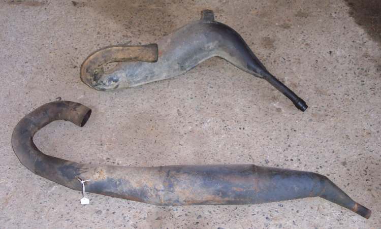
Servicing Small-Engine Exhaust Systems
Exhaust systems require little maintenance. The function of an exhaust system is to get rid of the exhaust gases from the internal combustion process going on in the engine. Depending on what type of implement the small engine is powering, the exhaust system may have a spark arrestor or a muffler that requires periodic service.
Servicing Spark Arrestors
A spark arrestor on a small engine does just that: It arrests — or stops — sparks from leaving the combustion chamber and entering the outside atmosphere. Spark arrestors are especially important on equipment, such as chain saws and trail bikes, that is used around combustible trees and brush. In fact, spark arrestors are required equipment on some small engines in many states.
A spark arrestor is simply a screen on the exhaust port of a small engine. It is designed to stop sparks from exiting the engine. Use the following steps to service a spark arrestor:
Step 1: Make sure the engine is fully cooled and the ignition switch is off.
Step 2: Find the spark arrestor on the side of the engine. It is a screen or a short tube located wherever the exhaust gases exit the engine. Visually inspect the spark arrestor for blockage or damage. If any is found, remove the spark arrestor and clean or replace it.
Step 3: Tighten all nuts on the spark arrestor bracket and the exhaust system.

.
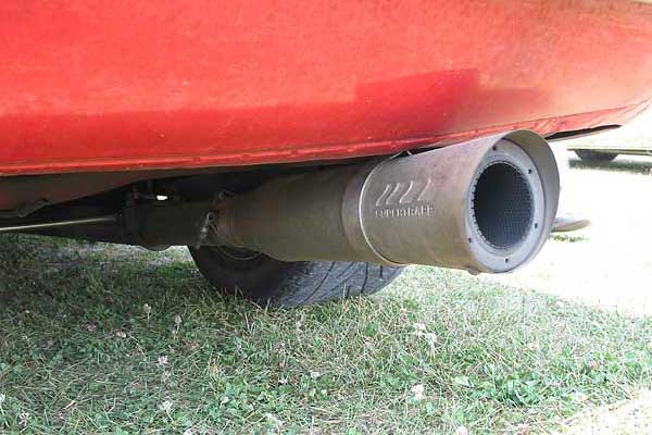
Servicing Mufflers
Mufflers are designed to reduce noise levels on small gas engines. Operating a small engine for any length of time without a muffler will sell you on the value of this device!
Fortunately, exhaust mufflers require no regular servicing beyond a visual inspection. Here’s how to service a muffler:
Step 1: Make sure the engine is fully cooled and the ignition switch is off.
Step 2: Find the muffler on the side of the engine where the exhaust gases exit. Use the end of a screwdriver to lightly strike the muffler at various locations, checking for rust damage or loose nuts. Also check the end of the muffler to ensure that there is no obstruction to exiting gases.
Step 3: Tighten all nuts on the muffler bracket and the exhaust system.

Servicing Small-Engine Controls
Small engines are used to power a wide variety of tools and toys. Controls make engines and their driven devices go faster or slower, turn on or off, change gearing, and make other operating adjustments. Servicing small engines requires servicing these controls as well.
In most cases, servicing controls means adjusting or lubricating them. Some controls are electrical (switches) while others are mechanical (throttles and gear selectors).
Adjusting Controls
Adjusting controls on a small engine typically requires the owner’s manual or a service manual for the specific model. That’s because control adjustments are frequently unique to that model. However, if you don’t have an owner’s manual, mechanical controls can be adjusted following commonsense procedures. Here’s how to adjust a throttle control:
Step 1: Make sure the engine is off and cooled before working on it.
Step 2: Inspect the control cable for kinks, bare spots, or other visible damage. At the same time, wipe oils and debris from the control cable and lever.
Step 3: Inspect both ends of the control cable, checking the connection to the throttle lever as well as to the carburetor or governor. Make sure both ends are securely fastened.
Step 4: Move the throttle lever back and forth as you watch the movement of the carburetor connection. If full lever movement doesn’t fully move the carburetor throttle, adjust the cable as required. In some cases, a fastener on or near the carburetor holds the throttle casing in place while allowing the throttle wire to move. Move the casing as needed and tighten the fastener.
Step 5: Lubricate the control before reassembly.
Lubricating Controls
Mechanical controls on engine-driven devices require periodic lubrication to minimize binding and wear. Here’s how to lubricate a cable control:
Step 1: Disconnect one end of the control wire to allow free movement within the cable. Apply spray or grease lubricant to the wire, making sure lubricant doesn’t reach other parts. Wipe away excess lubricant.
Step 2: Check the control for correct action. If adjustment is required, follow the procedures for adjusting controls.
By using the service guidelines mentioned in this article, you can keep your small engine working properly and save yourself time and money.
Related articles
How to Repair a Small-Engine part 2 -Ignition System (hydro-carbons.blogspot.com)
How to Repair Small Engines part1-Small Engine Basics (hydro-carbons.blogspot.com)
3 stroke engine – cross over between 2stroke and 4stroke engine (hydro-carbons.blogspot.com)
How to Repair a Small-Engine Lubrication System (hydro-carbons.blogspot.com)
Spark Plug- Tune-up (hydro-carbons.blogspot.com)
2 Stroke Engine Troubleshooting And Tips – Basics (hydro-carbons.blogspot.com)
Achieving Better Fuel Economy and High Performance with Gasoline Direct Injection (hydro-carbons.blogspot.com)

 Harley-Davidson LR-64 Rocket. ~ Grease n Gasoline(greasengasoline.wordpress.com)
 IMME R100(RIEDEL) 1950 ~ Grease n Gasoline(greasengasoline.wordpress.com)
 2013 BMW HP4 MOTORCYCLE ~ Grease n Gasoline(greasengasoline.wordpress.com)
 The Killinger and Freund Motorrad ~ Grease n Gasoline(greasengasoline.wordpress.com)
 2013 Porsche 911 Carrera 4 and 4S ~ Grease n Gasoline(greasengasoline.wordpress.com)
 MOTO GUZZI DIABOLA V35 C ~ Grease n Gasoline(greasengasoline.wordpress.com)
 COMPARISON OF YAMAHA R15 VERSION 2.0 vs 2012 HONDA CBR 150R ~ Grease n Gasoline(greasengasoline.wordpress.com)
 V-rod Cafe Racer(hydro-carbons.blogspot.com)
 Wireless Headsets For Motorcycle Helmets ~ Grease n Gasoline(greasengasoline.wordpress.com)
 X132 Hellcat Combat Prototype ~ Grease n Gasoline(greasengasoline.wordpress.com)