260cc Radial Engine

Seven Cylinder 4-Stroke Radial Engine 260cc Petrol

 Seven Cylinder 4-Stroke Radial Engine 260cc Petrol
Features
Cylinder head and crank cases produced from aircraft grade alloys to assure tight tolerances and great performance
The dual ball bearings and forged steel crankshaft provide the durability required from heavy power requirements
Billet aluminium pistons add to the precision of the engine and hardened steel rings add to the durability
Hard chromed and lapped cylinder bores add longevity, assure good oil coverage and a quicker break-in process for the ring
The single cam ring is made from hardened steel for low wear and long life
Carburetor jet valve incorporates the latest design with a split opening for smooth acceleration

Seven Cylinder 4-Stroke Radial Engine 260cc Petrol

Specification
Type Spark Ignition
Cylinders 7
Capacity 15.9 cu. In  –  260.0cc
Capacity per cylinder 2.26 cu in.  – 37.1cc
Bore 1.41 in.  –  35.7mm
Stroke 1.46 in.  –  37.0mm
Power 12.8hp
RPM Range 1000-5500
Maximum RPM 6300
Engine Diameter 12.6 inches  (32 cm)
Weight 14.8 lbs (6.7kg)

1903 PREMIER ENGINE

1903 Premier-Engine-vintage-car-rare-overhead-cam-gear driven-rare vintage car design

ENGINE DESIGNS | The 1903 Premier engine had a gear-driven overhead cam, roller cam followers, and crossflow hemi heads.
Very Rare Vintage Car Engine Made by Premier Motor Manufacturing Company

15 PICS ENGINE DESIGNS | VON DUTCH

MOTORCYCLE ENGINE DESIGNS HAND SKETCHES BY  VON DUTCH
MOTORCYCLE ENGINE DESIGNS HAND SKETCHES BY  VON DUTCH

MOTORCYCLE ENGINE DESIGNS HAND SKETCHES BY  VON DUTCH

MOTORCYCLE ENGINE DESIGNS HAND SKETCHES BY  VON DUTCH

MOTORCYCLE ENGINE DESIGNS HAND SKETCHES BY  VON DUTCH

MOTORCYCLE ENGINE DESIGNS HAND SKETCHES BY  VON DUTCH

MOTORCYCLE ENGINE DESIGNS HAND SKETCHES BY  VON DUTCH

MOTORCYCLE ENGINE DESIGNS HAND SKETCHES BY  VON DUTCH

MOTORCYCLE ENGINE DESIGNS HAND SKETCHES BY  VON DUTCH

MOTORCYCLE ENGINE DESIGNS HAND SKETCHES BY  VON DUTCH

MOTORCYCLE ENGINE DESIGNS HAND SKETCHES BY  VON DUTCH

IMAGES COURTESY OF ARIEL MOTORCYCLES

1909 Torpedo V4 Replica [ VIDEO ]

More photos and video below : 1909 Torpedo V4 Replica ( SUMMARY ~ 1909 Torpedo V4.Pavel created this bike from scratch. The finished Motorcycle  is a beauty, especially the engine, which, though called a V4, is more like a partial radial. The 1600cc mill is actually two conjoined V-Twins from Trojan & Nagl, )

1909 Torpedo V4 Replica 1909 Torpedo V4.Pavel created this bike from scratch. The finished bike is a beauty, especially the engine, which, though called a V4, is more like a partial radial. The 1600cc mill is actually two conjoined V-Twins from Trojan & Nagl,

A well known restorer from Czech Republic, Pavel Malanik teamed up with his friend Josef Kubista to reproduce a celebrated motorcycle of the yesteryear, the Trojan & Nagl V-4 motorcycle. The Trojan & Nagl Company was based in Kolin that was part of the Austro Hungarian Monarchy and had built a steady reputation of building one and two cylinder bicycles and motorcycles. A three cylinder Trojan and Nagl engine was also believed to have been used in one of the earliest versions of the helicopter in the year 1912.  

1909 Torpedo V4 Replica by Pavel Malaník

1909 Torpedo V4 Replica by Pavel Malaník

1909 Torpedo V4 Replica by Pavel Malaník

1909 Torpedo V4 Replica by Pavel Malaník


IMAGE COURTESY PAUL CROWE – “THE KNEESLIDER”

INTERESTING BEER KEGS

 INTERESTING MOTORCYCLE ENGINE BEER KEGS  
MADE OUT OF MOTORCYCLE ENGINES
 INTERESTING MOTORCYCLE ENGINE BEER KEGS   MADE OUT OF MOTORCYCLE ENGINES

 INTERESTING MOTORCYCLE ENGINE BEER KEGS   MADE OUT OF MOTORCYCLE ENGINES

 INTERESTING MOTORCYCLE ENGINE BEER KEGS   MADE OUT OF MOTORCYCLE ENGINES
GREASE n GASOLINE 
DO NOT DRINK AND DRIVE / RIDE 

Running Kerosene in a Gasoline Engine

This is a subject seen often in antique engine and tractor forums, and quite a few seem to be interested (especially in the small engine crowd). I am an antique small engine enthusiast who became interested in this subject a number of years ago. When I asked questions, I found few answers. I kept at it and did my homework, so now I’m writing the article I wish I’d found 5 years ago. Hopefully I can clear the air a little on this issue…


In order to burn “distillate fuels” like kerosene or diesel, first, it must be atomized/vaporized. Either mechanically (like a diesel injection pump) or with heat. Any gasoline engine can be set up to run on kerosene as long as two issues are addressed, how to prevent preignition, and how to vaporize the fuel.


First, lets deal with fuel vaporization. I’ll begin with a brief discussion on the characteristics of gasoline vs. kerosene vs. diesel. All of these are petroleum distillates, which means they are refined from crude oil. As with any distillation process, the “lighter” elements are the first to evaporate. Gasoline is one of these elements. Diesel is considered a “heavier” element, which means it does not evaporate easily. Kerosene is roughly between the two. So here is a very simplified comparison.


Gasoline: 125,000BTU/gal. Flashpoint is -40F


Kerosene: 135,000BTU/gal. Flashpoint is 100-162F


Diesel: 138,000BTU/gal. Flashpoint is 126-204F


The key factor here is the flashpoint, which is the minimum temperature at which the fuel will vaporize with air to produce a combustible mixture. Note the jump from gasoline to kerosene is at least 140 degrees! Diesel’s flashpoint is as much as 240 degrees higher! The reason for this is the hydrocarbon “chain” of molecules is much longer in kerosene and diesel than in gasoline. This chain must be broken apart before the fuel will vaporize. The easiest way to accomplish this is HEAT.


Another important thing to remember is the difference between “atomization” and “vaporization”. To keep this a simple explanation, atomization is the conversion of a liquid to a fine mist, and vaporization is the conversion of liquid to a gaseous form. Why am I boring you with this? Because in order to effectively burn “middle distillates” like kero or diesel, they must be VAPORIZED. Fuel that is too cool will be atomized by a carburetor. The result is the poor, very smoky performance that some of us experimenters have seen. When the microscopic droplets of fuel are burned, only that fuel which is actually vaporized will burn. The rest either sticks to the cylinder head as carbon, or goes out the exhaust as smoke. This is great for ‘skeeter control, but it is a waste of fuel and not the best for your engine. Heat must be used to vaporize these heavier fuels.


Since the goal of running kerosene was to reduce operating expenses (years ago anyway), mechanical atomization (as in a diesel engine) is out of the question. Also, whatever method used needs to be simple and low maintenance. So for simplicity and minimizing cost, heat is the method of choice. On the tractor engines of old, this was easy since most integral intake/exhaust manifolds had a “hotspot” where the exhaust manifold heated the intake manifold immediately downstream of the carburetor. The fuel in the intake stream that was not completely vaporized would not be able to make the sharp turn into the intake manifold log and would be thrown into this very hot surface and immediately vaporize. Even automotive engines used this in the form of an exhaust crossover in V8 intake manifolds, and the same “hotspot” style was used on inline sixes. The principle is used on gasoline engines to improve efficiency and cold weather operation. In some cases, the fuel line from the kerosene tank was run in close proximity to the exhaust manifold to preheat the fuel so it would vaporize more readily in the carburetor.


The second problem with kerosene and diesel in a gasoline engine is preignition. Kerosene and diesel have a very low octane rating (somewhere around 25) and thus makes it very prone to compression ignition. This is why, of course, they run great in diesel engines. In a diesel, the fuel is not introduced until it is time to burn it, so the low octane is a non issue. When the intake air is carrying the fuel, low octane is a problem. There are two ways to resolve this. The simplest, and most common, is to use a low compression ratio so that the intake air will not be compressed enough to ignite the fuel. Any engine with a ratio of around 6.5:1 or less should be able to run kerosene without problems. This would include almost every flathead engine made, as well as a good number of antique tractor I-head engines. Another slightly more complicated option is to use an anti detonant. The best example of this would be the Rumely Oil Pull engine. It utilized a three bowl carburetor. One for starting gasoline, one for kerosene, and one for water. The water jet was located ahead of the venturi (where the main jet is located) so that water was only drawn when the engine was under load (half throttle or above). The water prevented compression ignition thus allowing higher compression ratios to give performance equal to (some will argue better than) a gasoline engine of equal size. Another advantage to the water/kero mix is it produces a much smoother (less violent) burn in the cylinder, making it much easier on the engine. Therefore, it lasts longer. For more information on the Secor-Higgins carburetor, follow this link to a fantastic article on the “Rusty Iron” webpage.


http://rumely.rustyiron.com/secor.html


There were a surprising number of OEM small engines built for gasoline/kerosene operation by Kohler, Briggs & Stratton, Clinton, and Tecumseh. All were off the shelf gasoline engines modified for kerosene operation. These modifications included:


1. Either a low compression cylinder head, or a stock head installed with two head gaskets.


2. A divided fuel tank with the large side for kerosene, and a small (usually a pint or less) for starting/warm-up gasoline. In some cases, the bowl capacity or the fuel bowl in the carburetor had sufficient capacity for an adequate amount of gasoline to start the engine, so a small flip top “fill cup” was T’d into the fuel line so that the carburetor bowl could be filled with gasoline prior to starting.


3. A carburetor bowl drain of some fashion for draining kerosene from an improperly shut down carburetor. On Briggs “Flo-Jet” (updraft) carburetors, a special main jet screw was installed with a drain cap that allowed the bowl to be drained. Most other engines with stamped metal bowls used a small button installed in a drilled hole in the bottom of the bowl. These are still used on some Tecumseh “Sno-King” and other engines for seasonal use.


4. A hotter spark plug was utilized to prevent fouling, and in some cases (on the Kohlers) timing was retarded to aid in the prevention of detonation.


The fuel heating on small engines is inherent in the design. The close proximity of the intake to the exhaust on most L-head single cylinders heats the intake elbow sufficiently to somewhat vaporize kerosene. Diesel fuel would be slightly more difficult since the hydrocarbon chain is longer than that of kerosene. Pretty much any single cylinder L-head engine with a float bowl carburetor should not be difficult to convert for kerosene use.


Opposed twins like Onan’s CCK and Kohler’s K-582 (or the monstrous K_-662) will pose some problems due to the long intake runners sitting atop the engine right in the cooling air. The expense of designing and building a reliable kerosene system would probably negate the fuel savings advantage of kerosene. 


The old Briggs manuals state that engine’s horsepower must be derated by 15% when running on kerosene, and engines with “Vacu-Jet” and “Pulsa-Jet” carburetors (those mated directly to the fuel tank) cannot be converted for kerosene use.


If you are willing to do the research and design/build a kerosene carburetion system, a lot of the parts are still out there sitting on distributors shelves as “New Old Stock”. For example, Briggs & Stratton, and Kohler dual fuel tanks, brackets, and carburetor parts are waiting for someone to claim them. I know, because I have a few brand new Briggs gas/kero tanks sitting in my shop. Other items the OEMs used were simple brass and copper parts (three-way valves, fill cups, and other hardware) that are still available at most hardware stores. 


The bottom line is that in order to burn “middle distillates”, the fuel needs to be heated to the point where it will vaporize. To keep the fuel from knocking and destroying your engine, you need to lower the compression ratio and/or use an anti-detonant.


Hope my little treatise helps in some way. I did a lot of research on the subject a few years back and spent many hours researching on the web, reading books on petroleum chemistry, and poring over pages and pages of old parts/service manuals on a microfiche viewer. I hope it sparks interest and saves folks who are interested in this some time and headache.


-Eric

1922 Peugeot Grand Prix Racer

1922 Peugeot Grand Prix Racer
Claimed power: 27hp @ 5,000rpm
Top speed: 100mph (approx.)
Engine: 495cc air-cooled SOHC parallel twin
Weight (dry): 286lbs


Ask your local bike trivia champions when the first double overhead cam eight-valve vertical-twin was produced and by whom. Chances are they won’t even get the country right — and they probably won’t believe you when you tell them the answer: the 500cc 1913 Peugeot Grand Prix, designed by the brilliant Swiss engineer Ernest Henry.


Peugeot history 
Peugeot lays valid claim as the world’s oldest surviving motorcycle marque, as the company displayed its first bike — the 1.5hp Motobicyclette — at the Paris Exhibition in 1900. Peugeot originally used supplier engines to power its way into the fledgling motorcycle industry, but in 1906 began using its own large capacity (726cc and 994cc) V-twin engines, essentially derived from their car designs. These proved so powerful and reliable that Peugeot’s reputation swiftly grew outside France, resulting in deals to supply other manufacturers with Peugeot engines.


Two of these were British — while the record books tell us that Rem Fowler rode a Norton to win the first-ever Isle of Man TT in 1907, it was powered by a Peugeot engine. Similarly, a pair of Peugeot-engined, British-built NLGs finished first and second in the inaugural motorcycle race at the new Brooklands track in 1908.


Spurred on by these two-wheeled successes, Peugeot decided to construct its own Grand Prix motorcycle racer, employing the latest in automotive and aviation engine technology, of which its designer Ernest Henry was a proven master. In 1913 he produced the world’s first double overhead cam eight-valve parallel-twin motorcycle, the 500cc Peugeot GP racer that, while unquestionably fast and decades ahead of its time, suffered problems with cylinder head cooling.


Development was interrupted by World War I, and when racing began again in 1919 Peugeot developed a completely new, less complicated design that swept all before it.


Saved and restored 
Jean Nougier’s 1922 Peugeot Grand Prix racer shares the same engine dimensions as its pre-WWI double overhead cam sister, measuring 62mm x 82mm for a total capacity of 495cc, and produces 27 horsepower at 5,000rpm. The hefty outside flywheel helped deliver good torque at low revs, and together with the dry sump engine design permitted a strong, narrow crankcase for good crankshaft rigidity, with three main ball bearings. Exposed coil springs and two valves per cylinder — note the parallel exhaust ports — were actuated by a massive vertical shaft running off the right end of the crank. The top bevel housing must have been dealt more than a few mighty blows in the course of a race by the rider’s hand, since the knob of the three-speed gearbox’s hefty hand-shift lever sits about an inch away from it. Remarkably for the time, the Peugeot is a unit-construction engine with gear primary drive and a two-plate dry clutch. Magneto ignition and a single carb with siamesed inlet ports complete the engine specification.
The Peugeot’s rigid frame was almost as advanced for the era as its engine, consisting of a double cradle chassis with twin top tubes and vertical seat pillar, to which the slim oil tank is affixed. The steering head is braced for extra stiffness, and is fitted with Druid-type girder forks with side friction dampers. Apparently, the French bikes handled very well by the standards of the day, confirmed by Jean Nougier after parading the bike in his local Avignon street circuit’s retro celebrations. “The performance can be compared to a good Triumph twin-cylinder roadster from the 1950s,” he told me years ago, “once you get over the handicap of the gear change, which isn’t easy to use. But the acceleration is quite brisk, and the straight exhaust pipes mean it pulls cleanly out of slow corners. And for la periode des annees Vingt (the period of the Twenties), the braking is not too bad,” Nougier said.

Read more: source

Related articles

Enhanced by Zemanta

Recommended engine break-in procedure

 Motorcyclist magazine asked four of the top engine builders in the country what they do to ensure peak power output and optimum engine life. This is most of the article, (all of the break–in procedure).


From MOTORCYCLIRecommended engine break-in procedure

Motorcyclist magazine asked four of the top engine builders in the country what they do to ensure peak power output and optimum engine life. This is most of the article, (all of the break–in procedure).

From MOTORCYCLIST Feb. 1991. titled GIVE IT A BREAK-IN (How to make your bike run stronger and live longer).

The first few hundred miles of a new engine’s life have a major impact on how strongly that engine will perform, how much oil it will consume and how long it will last….. We ask four top engine builders what they do to ensure peak power output and optimum engine life……….piston ring and cylinder seating is critical to get a proper seal for power output and oil consumption…..If the wrong type of oil is used initially or the breakin is too easy, rings and cylinders could glaze and never seal properly. A fresh cylinder wall needs some medium to high engine loadings to get the piston rings to seat properly for good compression but don’t lug or overheat the engine either. 

 Use high quality low viscosity oil (Valvoline 30 weight eg.) no synthetics, too slippery, if used during initial breakin the rings are sure to glaze. Initial run should be used to bring oil and coolant up to temperature only, with little or no load, then shut off and allow to cool right down. After thorough cool down (ambient temp), start up and ride under light loads at relativly low rpm 3000-5000 rpm, keep out of top gear, lugging is more detrimental than high rpm. Key advice, constantly vary load on engine, a constant load is not ideal for breaking in bearing tolerances. This run should last only 10-15 minutes before another complete cool down.

 The next run should be slightly higher rpm, 5000-7000 and under light to medium loads using short bursts of acceleration to seat the rings in early. Again 10-15 minutes of running should do it and again avoid top gear. Allow to cool right down. The third run should consist of light to medium engine loads with a few more bursts of medium-high rpm, 8000-9000 rpm max, and lasting just 10-15 minutes varying the engine load and avoiding top gear. Next while the engine is still warm drain the oil and change the filter. This gets out the new metal particles that are being worn away. Al Ludington from Vance and Hines feels most of the metal particles will break away within first 50 -75 miles, get them out soon after. To ensure the rings seat well, use same high quality oil and don’t be shy about short duration high rpm blasts through the lower gears after the oil has been changed. A few more 15-20 minute sessions should be used to work up to the engine’s redline gradually increasing the engine loads. After some definite hard running and 250-500 miles it’s a good idea to check the valves. After 500 miles retorquing the head is suggested. Switch to snythetic oil but not before 500-1500 miles. Most of the engine experts warned of the danger of breaking in the engine too easily and ending up withwith an engine that will always run slow whether it is from tight tolerances, inadequate ring seal or carbon buildup. Engine load is more detrimental than rpm, so avoid lugging the engine but rev it freely especially in the lower gears. Muzzy summed up his break-in concerns most concisely: Basically, be sure not to get it too hot but be sure to seat the rings properly. Its that simple………..


So that’s it, sure a lot different than keeping under 4000 rpm for 500 miles then under 5000 rpm for 1000 miles. Maybe bike manufacturers are being super cautious at the expense of your motor’s performance? I think that they take the cautious route that works over time (1000 miles, or about 20 hours of break in) versus a faster route that can be more easily screwed up. FWIW, on the VF1000R, the slower break-in showed better leakdown at 4000 miles than at 1500, and I suspect that the go-slow method of the factory recommendations are looked at more for simplicities sake than for other effects.ST Feb. 1991. titled GIVE IT A BREAK-IN (How to make your bike run stronger and live longer).

The first few hundred miles of a new engine’s life have a major impact on how strongly that engine will perform, how much oil it will consume and how long it will last….. We ask four top engine builders what they do to ensure peak power output and optimum engine life……….piston ring and cylinder seating is critical to get a proper seal for power output and oil consumption…..If the wrong type of oil is used initially or the breakin is too easy, rings and cylinders could glaze and never seal properly. A fresh cylinder wall needs some medium to high engine loadings to get the piston rings to seat properly for good compression but don’t lug or overheat the engine either. Use high quality low viscosity oil (Valvoline 30 weight eg.) no synthetics, too slippery, if used during initial breakin the rings are sure to glaze. Initial run should be used to bring oil and coolant up to temperature only, with little or no load, then shut off and allow to cool right down. After thorough cool down (ambient temp), start up and ride under light loads at relativly low rpm 3000-5000 rpm, keep out of top gear, lugging is more detrimental than high rpm. Key advice, constantly vary load on engine, a constant load is not ideal for breaking in bearing tolerances. This run should last only 10-15 minutes before another complete cool down. The next run should be slightly higher rpm, 5000-7000 and under light to medium loads using short bursts of acceleration to seat the rings in early. Again 10-15 minutes of running should do it and again avoid top gear. Allow to cool right down. The third run should consist of light to medium engine loads with a few more bursts of medium-high rpm, 8000-9000 rpm max, and lasting just 10-15 minutes varying the engine load and avoiding top gear. Next while the engine is still warm drain the oil and change the filter. This gets out the new metal particles that are being worn away. Al Ludington from Vance and Hines feels most of the metal particles will break away within first 50 -75 miles, get them out soon after. To ensure the rings seat well, use same high quality oil and don’t be shy about short duration high rpm blasts through the lower gears after the oil has been changed. A few more 15-20 minute sessions should be used to work up to the engine’s redline gradually increasing the engine loads. After some definite hard running and 250-500 miles it’s a good idea to check the valves. After 500 miles retorquing the head is suggested. Switch to snythetic oil but not before 500-1500 miles. Most of the engine experts warned of the danger of breaking in the engine too easily and ending up withwith an engine that will always run slow whether it is from tight tolerances, inadequate ring seal or carbon buildup. Engine load is more detrimental than rpm, so avoid lugging the engine but rev it freely especially in the lower gears. Muzzy summed up his break-in concerns most concisely: Basically, be sure not to get it too hot but be sure to seat the rings properly. Its that simple………..

So that’s it, sure a lot different than keeping under 4000 rpm for 500 miles then under 5000 rpm for 1000 miles. Maybe bike manufacturers are being super cautious at the expense of your motor’s performance? I think that they take the cautious route that works over time (1000 miles, or about 20 hours of break in) versus a faster route that can be more easily screwed up. FWIW, on the VF1000R, the slower break-in showed better leakdown at 4000 miles than at 1500, and I suspect that the go-slow method of the factory recommendations are looked at more for simplicities sake than for other effects.


Enhanced by Zemanta

Achieving Better Fuel Economy and High Performance with Gasoline Direct Injection

Trying to choose between performance and economy is often a very difficult decision, and usually there has to be a compromise between the two. However, one technology is helping to power gasoline engines to new heights of performance, while pushing fuel mileage forward by leaps and bounds: gasoline direct injection. The photos below from Bosch illustrate the key elements of a gasoline direct injection system.


Back in the Day

Direct fuel injection is not a new idea. Diesel engines have always used the technology, which squirts fuel under high pressure into an engine’s cylinders rather than into the intake manifold. In a diesel engine, the process of injecting fuel directly into the combustion chamber at the top of the compression stroke initiates and controls combustion. The Robert Bosch Company perfected the modern mechanical injection pump for small diesels in Germany in 1927.
Bosch developed the first automotive direct injection system using gasoline, and Mercedes introduced it on the 1955 Mercedes Benz 300SL. Engine power was double that of its carbureted counterparts and allowed a top speed of up to 161 mph, making it the fastest production car of its time.

How Direct Injection Works

It might be easiest to see how direct injection works by comparing it to traditional fuel injection methods. With conventional fuel injection, injectors supply all cylinders with a mist mixture of air and fuel, averaging a constant 14.7:1 ratio, known as astoichiometric mixture. Vacuum draws the mixture into the cylinder where the spark plug ignites it. The throttle valve determines how much of the air/fuel mixture enters each cylinder, keeping the mixture at an optimum 14.7:1 ratio. Lean air/fuel mixtures won’t ignite well, creating excessive NOx and hydrocarbon emissions which the catalytic converter must then capture and process.
In a direct injection engine, the injection nozzle is located inside the combustion chamber and injects a finer spray, like that from an atomizer bottle. Each solenoid-controlled injector has minute outlet holes which exude a fine mist. Injectors positioned to the side of each cylinder, aim the fuel into the cylinder, adjacent to the spark plug, and alongside the intake and exhaust valves.

Like an atomizer bottle spray, the fine mist generated by each solenoid-controlled injector’s tiny outlet holes creates a well-atomized air/fuel mixture. Injectors spray fuel into the cylinders at pressures of up to 2,150 psi, about 35 times more intense than port fuel injection. (Courtesy of Bosch.)

A high-pressure fuel rail feeds each bank of cylinders using individual injectors and a fuel rail pressure sensor to help the powertrain control module precisely control fuel pressure. Some systems fire the injectors multiple times during one injection event at pressures of up to 2,150 psi, which is about 35 times more intense than port fuel injection.

Each bank of cylinders has a high-pressure fuel rail that feeds the individual injectors, and a high-pressure pump with a rail pressure sensor that helps the vehicle powertrain control module precisely control fuel pressure. (Courtesy of Bosch.)

When the injectors spray fuel into the cylinder, a relatively small, precisely-shaped volume of ignitable air/fuel mixture surrounds each spark plug. Areas inside the combustion chamber, but away from the spark plug, merely contain air or recirculated exhaust gas. This stratification of the charge allows the engine to burn mixtures with a much higher rate of air than conventional engines. The cushion of non-combustible gas around the combustion chamber also means less combustion heat to evacuate. This improves the thermal efficiency of the engine, increasing fuel economy.

To control injection valves, new common-rail injectors use a rapid-action actuator made of piezo crystals. Piezo package movement is transmitted non-mechanically and without friction to the rapidly switching nozzle needle. This doubles the injector’s switching speed, allowing a more precise measurement of fuel injected, and thus reducing harmful combustion by-products.  (Courtesy of Bosch.)

Since direct injection charge stratification works best at low and medium loads in the lower half of the engine speed range where traditional gasoline engines are least efficient, it allows direct injection engines to obtain up to 21 percent better fuel economy.

How Working Together Improves Performance and Economy

The future of direct injection involves coupling the system with other technologies, such as turbocharging and automatic engine stopping and restarting. By integrating multiple technologies, automakers can develop smaller, more fuel-efficient engines, while improving performance.
Turbocharging direct injection engines is a promising fuel economy technology. A turbocharged, direct-injection engine combines existing and proven technologies, allowing manufacturers to meet future emission standards using existing catalytic converters. Automakers can apply this technology across a manufacturer’s entire engine portfolio, including flexible fuel applications.
Other technologies maximize direct injection engine thermodynamics. In economy mode, an insulating blanket of air and recirculated exhaust gas helps keep heat away from the cylinder walls and head. In high-powered mode, the engine creates more heat. By controlling the operating speed of the water pump, especially during economy mode operation, a reduction in drag on the engine provides improved fuel economy. Variable intake and exhaust timing is especially efficient with gasoline direct injection and turbocharging systems. The variable engine timing enabled by camshaft phasing can optimize the combustion process. Also, valve overlap at low rpm can be adjusted by the engine controller to increase the turbocharger response, reducing turbo lag.

Servicing

With almost every manufacturer offering at least one direct injection engine, technicians should be seeing these vehicles in their bays for service.
“The biggest item to consider when servicing (direct injection) systems is the high voltage and fuel pressures the systems generate,” says Al Krenz, director of service for Bosch North America. A direct injection system typically will operate between 725 psi up to 2050 psi, so bleeding down the fuel system properly is important.”
“Always follow the manufacturer’s procedure to relieve the fuel system before performing any repairs to the system,” Krenz recommends.
Carefully diagnose the fuel injector voltage signals. High-pressure injectors typically actuate at approximately 70 volts and 10 amps, with the capability to rise over 120 volts.
As with diesel direct injectors, carbon can build up on the injector tip and interfere with fuel distribution and atomization. While typical port injectors produce a fuel droplet of approximately 165 microns, direct injectors atomize a much smaller fuel droplet size of only 65 microns, so even the slightest loss of fuel delivery will adversely affect engine drivability, power output, fuel economy and exhaust emission.

Enhanced by Zemanta

Performance Mufflers: Theory-of-Operation and Selection

As published in British V8 Newsletter, Volume XV Issue 2, September 2007

by: Larry Shimp

The focus of this article is on the silencing efficacy of an exhaust system, and how to get the minimum sound with the minimum flow restriction. This may not be of interest to everyone, but for those who want to drive for long distances, especially with air conditioned cars and closed windows, this may be more applicable. 

Source of noise:
The combustion process and exhaust cycle of the engine impart vibrations to the air stream that make themselves known as noise. Noise tends to increase in volume as an engine gets bigger and as compression increases, and to increase in frequency (and volume) as engine RPM is increased.

Muffler principles:
There are four main performance muffling principles: expansion, “turbo”, noise cancellation, and noise absorption. Old OEM mufflers worked primarily by restriction, but these will not be considered for performance use.

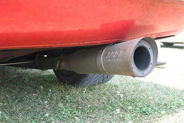
Dale Knapke’s Supertrapp mufflers utilize the expansion principle.
ExpansionExpansion is one of the oldest designs and works by letting the hot exhaust gases expand and cool so both their velocity and volume are reduced. These mufflers are simply long, big diameter tubes with no internal baffles, usually with an increasing diameter from the inlet to the outlet. As the exhaust gases slow down, the amplitude of the noise they carry is reduced. Expansion is relatively efficient in that the exhaust flow is not really hindered. Unfortunately, it is only practical for smaller, low power, low speed engines. It worked on Model T Fords and similar cars, but modern V8s put out too much exhaust volume for any reasonably sized expansion muffler to take care of.

However, hybrid expansion mufflers are still around. The megaphone mufflers seen on some motorcycles work by expansion in the increasing diameter exhaust tube, and by sound absorption in the fiberglass lining. This is also the fundamental principle of SuperTrapp mufflers (without the plates installed). At this year’s British V8 meet, Dale Knapke utilized SuperTrapp mufflers on his Ford SVO Turbo Triumph, and had good sound attenuation.


Leonard Marshall‘s Summit Turbo mufflers utilize the same noise canceling principles as OEM mufflers.
Chambered mufflers look externally similar, but utilize the “noise canceling” principle.


Turbo”Turbo mufflers” are a variation on OEM style mufflers, but are less restrictive, so they are in the performance category. They were originally developed for the early GM turbo cars (especially the Corvair) because the turbocharged engines didn’t like back pressure. Besides, the turbochargers already provided some muffling effect through expansion and cooling, so less sound attenuation was required from the mufflers. Turbo mufflers consist primarily of a pair of parallel, perforated dead-end tubes, sometimes with a baffle in between. Old style OEM mufflers are similar but usually have smaller tubes and less perforations, and sometimes extra baffles. The exhaust escapes from the holes in the inlet tube, and exits through the holes in the outlet tube. Noise cancellation is by restriction, which slows down the exhaust gasses, and by some noise cancellation as sound waves get reflected among the many inside surfaces. There is some case resonance, but the sound is otherwise similar to noise absorption mufflers.
ChambersNoise canceling is the principle used in chambered mufflers. A well known manufacturer of chambered mufflers is FlowMaster. (Although they externally resemble “turbo” mufflers, their internal construction is quite a bit diferent.) Chambered mufflers have a series of compartments that are designed to cause the sound waves to be reflected back on each other. Sound waves have peaks and valleys. If two waves are 180 degrees out of phase so that the peak of one wave corresponds with the valley of another wave, the peaks and valleys will cancel and the result is silence. Noise canceling ear phones work by electronically generating signals exactly 180 degrees out of phase to detected noise signals. The ultimate car interior cancellation system is therefore an electronic noise canceling circuit that sends counteracting sound waves through the car’s speaker system. This would let the driver determine the amount of interior noise at the turn of a dial. Prototype systems actually do exist, and I understand that some car companies were considering such a system for their production cars. 


Mufflers are not (at least not yet) electronic devices and so they must generate the canceling waves mechanically. At certain frequencies, some sound waves will cancel in this type of muffler. The range of frequency cancellation is often increased by having sloped baffles that will work on a variety of frequencies at once. Perfect cancellation is not needed in order to be effective, even partial overlap of the sound waves will result in a reduction in noise. Because the mufflers are limited in size, they mainly cancel higher frequency sound waves (the higher the frequency, the shorter the wavelength). This gives chambered mufflers their characteristic deep (low frequency) sound.

The main appeal of chambered mufflers is their sound characteristics. Low frequency sound is much less irritating than high frequency sound and that is why these mufflers are often described as “mellow”. Another characteristic of chambered mufflers is interior resonance. The sound within the muffler tends to vibrate the muffler case, turning it into what is, in effect, a speaker. This amplifies the sound inside the car and can be either an advantage or a disadvantage, depending on personal preference.

The main disadvantage of chambered mufflers is that they tend to restrict flow. This is a consequence of their sound wave reflection operating principle because as sound waves are reflected, so are actual exhaust gasses. However, they tend to be less restrictive than most turbo mufflers.

There are three ways to minimize this restrictive effect on performance. The first is to use as large a muffler as possible. But space in an MGB or similar car is very limited so this is not practical. The other is to place the muffler as far back from the engine as possible. In this position the exhaust gases have cooled as much as they can, and cool gases take up less volume; in effect giving the same outcome as a larger muffler. Many modern cars have their main muffler at the very rear of the exhaust system for this reason. However, space for an MG exhaust is very limited behind the rear axle, so this is not practical (but it may be practical for some cars like Triumphs). The third solution is to use an X pipe or an H pipe and a dual exhaust system. The connection between the pipes (before the mufflers) permits each exhaust pulse to use both mufflers, which gives the same effect as using a much larger muffler. Because the firing pulses in a V8 engine overlap to some extent (unless the engine has a single plane crankshaft), not every pulse has the whole exhaust system to itself, but the principle is still effective.

Car Chemistry brand mufflers are a variation on the out of phase noise canceling principle. They divide up the exhaust stream into two parts, and slow down one stream relative to the other. The velocity difference causes some out of phase variation in the sound waves between the two exhaust streams which results in some noise attenuation. For the maximum effect, the gas stream has to have a high inlet velocity, and so these mufflers are best installed as close to the engine as possible.

The Car Chemistry mufflers are not a good choice as a primary muffler because their overall sound attenuation is not as great as a conventional muffler. But they are useful as a supplement. These are available as a complete muffler, or as an insert that fits into the exhaust tubing. The inserts are the ultimate answer to ground clearance issues, but there is some restriction from the inserts. It is therefore best to oversize the exhaust tubing if using the inserts.


Al Wulf’s glass pack mufflers utilize the absorption principle.
AbsorptionAbsorption is the principle by which a glass-pack muffler works. There is a perforated tube within the muffler, and the sound radiates out through the perforations where it is absorbed by the fiber filler. Essentially, the sound is dissipated trying to vibrate the filler material and, in addition, the filler material does not reflect the sound waves back to the exhaust stream. Unlike chambered mufflers, these mufflers absorb sound at all frequencies and the result is the normal exhaust sound, only quieter. They will not produce a nice rumble like a chambered muffler without a lot of higher frequency noise accompanying it. The goal of an absorption muffler is as quiet a sound as possible; otherwise the higher frequency components of the sound can become annoying. One advantage is that, because most of the sound is absorbed before it gets to the outer case, the case resonates very little, and so interior resonance is generally less compared to a chambered muffler.

Absorption mufflers can be more efficient than chambered mufflers, but that depends on the design and installation. Many of these mufflers have a louvered internal tube. When the flow goes against the louvers, the sound is efficiently absorbed, but the louvers create turbulence that restricts flow. Turning the mufflers around greatly reduces turbulence, but it also greatly increases noise. Some mufflers, like the Magnaflow, have perforated tubes with plain holes and no louvers. These can be installed in either direction, and have the best compromise between flow restriction and sound absorption.

Of interest is that absorption mufflers both get louder and lose flow capability if the packing starts to come loose. Loose packing creates larger internal voids and this causes greater turbulence in the exhaust gases as they penetrate farther into the muffler outside of the main flow tube.
Additional IssuesMuffler configuration:
For the least noise it is always best to have two mufflers in series. The second muffler will absorb sound missed by the first muffler, and there will be some wave type noise canceling in the tubing between the two mufflers. Ideally, the second muffler should do most of the silencing but even a small resonator at the end of the exhaust system will make a big difference.

Exhaust outlet:
The exhaust outlet should extend beyond the separate bumper found on MGBs and most vintage sports cars. This is because the curved inner surface of the bumper will reflect the exhaust noise back towards the car contributing to “droning” during cruising. Another alternative is to used turned down exhaust tips to keep the noise away from the bumper/reflector.

Exhaust pipe size:
As a rule of thumb, a 2 inch dual exhaust is fine for a mild 215 engine, a 2 1/4 inch diameter is good for up to about 300 cubic inches, while a 2 ½ inch exhaust is good for a highly tuned 350. A 3 inch exhaust is better for larger performance engines. In theory, using too large of an exhaust can decrease low end torque because the increased gas velocity of a smaller pipe helps scavenging. However, I doubt this is too strong of an effect, and probably header diameter and length is more important for scavenging. But with an old British car, ground clearance is limited and that is a good reason for not using too large of a pipe.

In any case, the largest piping is needed before the X or H pipe. As was explained earlier, the X or H pipe allows the exhaust pulses to use both exhaust pipes, while the pulses are restricted to only one pipe before the cross over connection. Also, the exhaust gases have cooled slightly by the time they reach the cross over and will take up slightly less volume, but the cross over connection is the main effect. Logically, then, a way to minimize ground clearance issues and retain many of the advantages of a large diameter exhaust is to make a custom crossover piece with larger diameter inlet than outlet pipes.

To summarize, there are ways to make a quiet exhaust system without sacrificing power.

Disclaimer: This page was researched and written by Larry Shimp. Views expressed are those of the author, and are provided without warrantee or guarantee. Apply at your own risk.

Enhanced by Zemanta